OPERATION No MA.
450-00 : Ch
nrnclcrislics ortd sp~~c-i~l (c~c~trlrc>s 01 the hokiug S\ SI~IN
Op. MA. 450.00 5
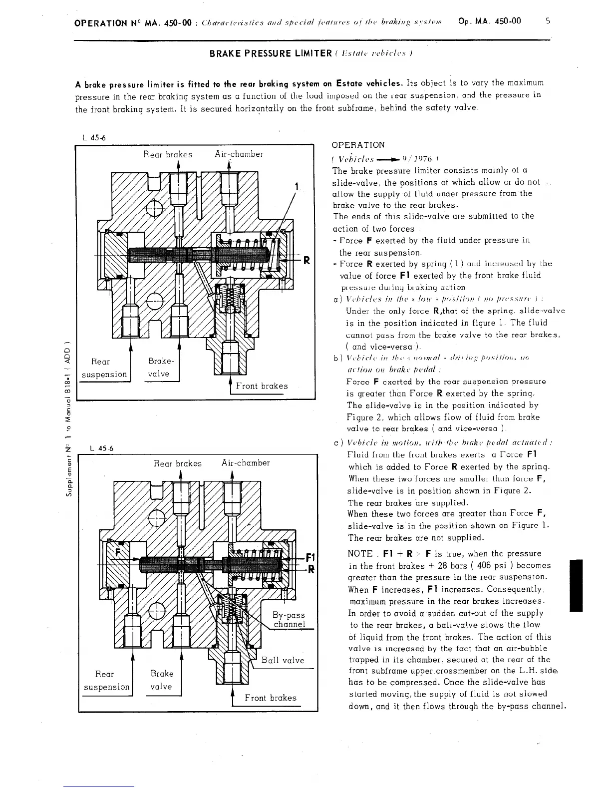
A brake pressure limiter is fitted to the rear braking system on Estate vehicles.
Its object is to vary the maximum
pressure in the rear braking system as a function of the load imposed on the rear suspension and the pressure in
the front braking system. It is secured horizontally on the front subframe, behind the safety valve.
L 45-6
Rear brakes
Air-chamber
A
Front brakes
Rear brakes
Air-chamber
A A
--
7 Front brakes
OPERATION
* I
f Vchtclcs -
‘I/]‘,?(, i
The brake pressure limiter consists mainly of a
slide-valve, the positions of which allow or do not
allow the supply of fluid under pressure from the
brake valve to the rear brakes.
The ends of this slide-valve are submitted to the
action of two forces
- Force
F
exerted by the fluid under pressure in
the rear suspension.
= Force
R
exerted by spring ( 1 ) and increased by the
value of force
Fl
exerted by the front brake fluid
pressure during braking action.
a) \‘~~I~i~-/~~s irt Ilte t( lorl r /tr,.silioti f t/o /trc~.s.surc’ )
Under the only force R,that of the spring. slide-valve
is in the position indicated in figure 1. The fluid
cannot pass from the brake valve to the rear brakes,
( and vice-versa ).
Force
F
exerted by the rear suspension pressure
is greater than Force
R
exerted by the sprinq.
The slide-valve is in the position indicated by
Figure 2. which allows flow of fluid from brake
valve to rear brakes ( and vice-versa ).
c ) Vvhiclc il2 ntotior/. rr,ith 111~’ broke pednl ncl~~fit~~c/ :
Fluid from the front brakes exerts a Force
Fl
which is added to Force
R
exerted by the spring.
When these two forces are smaller than force
F,
slide-valve is in position shown in Figure 2.
The rear brakes are supplied.
When these two forces are greater than Force
F,
slide-valve is in the position shown on Figure 1.
The rear brakes are not supplied.
NOTE
Fl
+
R
-b
F
is true, when the pressure
in the front brakes + 28 bars ( 406 psi ) becomes
greater than the’pressure in the rear suspension.
When
F
increases,
Fl
increases. Consequently,
maximum pressure in the rear brakes increases.
In order to avoid a sudden cut-out of the supply
to the rear brakes, a ball-valve slows the flow
of liquid from the front brakes. The action of this
valve is increased by the fact that an air-bubble
trapped in its chamber, secured at the rear of the
front subframe upper.crossmember on the L.H. side,
has to be compressed. Once the slide-valve has
started moving, the supply of fluid is not slowed
down, and it then flows through the by-pass channel.