FIG. 1
Supply to brake valve
Rear suspension
i \
Filter
\--Iii
I
Rear brak
. .
One-way valve
I
units
Rl
Feed to brake valve
F
Rear suspension
/
One-way valve
II
Rear brake
Rl Fl
units
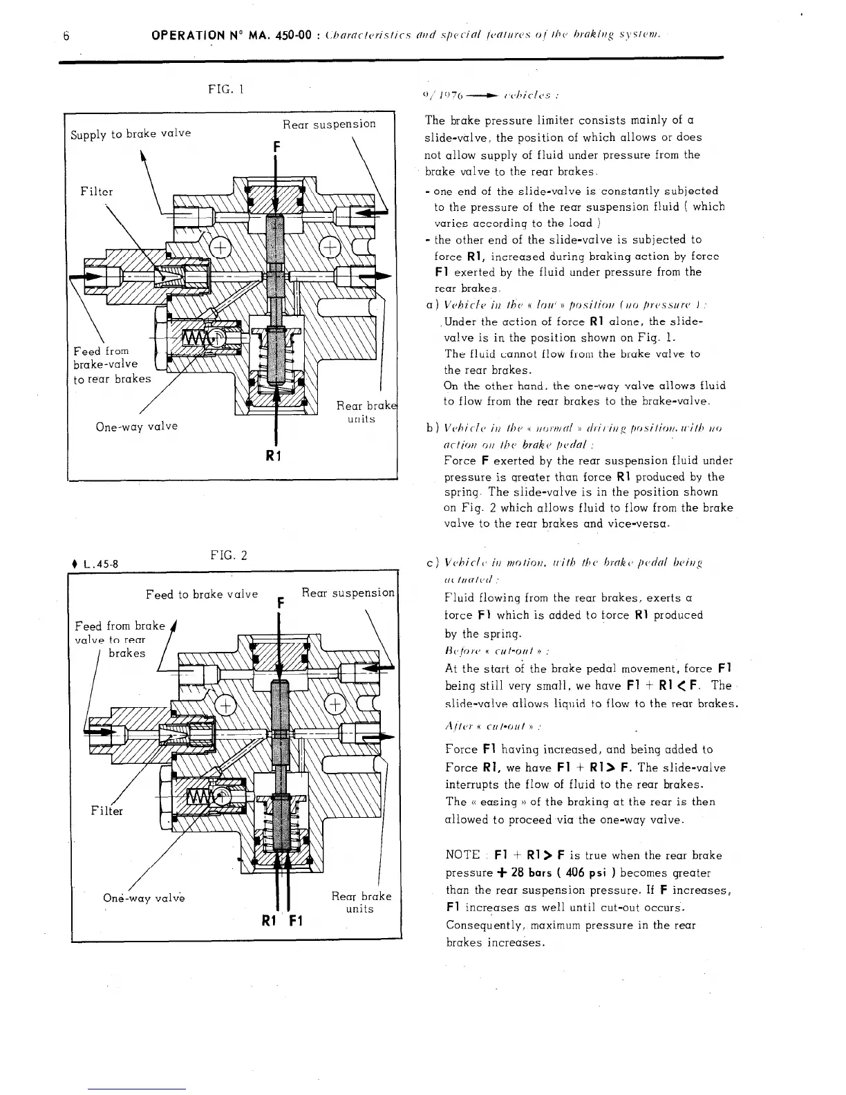
The brake pressure limiter consists mainly of a
slide-valve, the position of which allows or does
not allow supply of fluid under pressure from the
brake valve to the rear brakes.
-
one end of the slide-valve is constantly subjected
to the pressure of the rear suspension fluid ( which
varies according to the load )
- the other end of the slide-valve is subjected to
force
Rl,
increased during braking action by force
Fl
exerted by the fluid under pressure from the
rear brakes
a)
Vvhirlc, irl the n IOU N positiolt (,,o /)rc,.ssurc, )
.Under the action of force
Rl
alone, the slide-
valve is in the position shown on Fig. 1.
The fluid cannot flow from the brake valve to
the rear brakes.
On the other hand, the one-way valve allows fluid
to flow from the rear brakes to the brake-valve.
Force
F
exerted by the rear suspension fluid under
pressure is qreater than force
Rl
produced by the
spring. The slide-valve is in the position shown
on Fig. 2 which allows fluid to flow from the brake
valve to the rear brakes and vice-versa.
Fluid flowing from the rear brakes, exerts a
force
Fl
which is added to force
Rl
produced
by the spring.
H~prc 6
CNt’Out
11
At the start of the brake pedal movement, force
Fl
being still very small, we have
Fl t Rl < F.
The
slide-valve allows liquid to flow to the rear brakes.
Aitcr
t(
CIIIW~~
H
Force
Fl
having increased, and being added to
Force
Rl,
we have
Fl
+
Rl> F.
The slide-valve
interrupts the flow of fluid to the rear brakes.
The (( easing )) of the braking at the rear is then
allowed to proceed via the one-way valve.
NOTE :
Fl
+
Rl> F
is true when the rear brake
pressure +
28 bars
( 406 psi ) becomes greater
than the rear suspension pressure. If
F
increases,
Fl
Increases as well until cut-out occurs.
Consequently, maximum pressure in the rear
brakes increases.