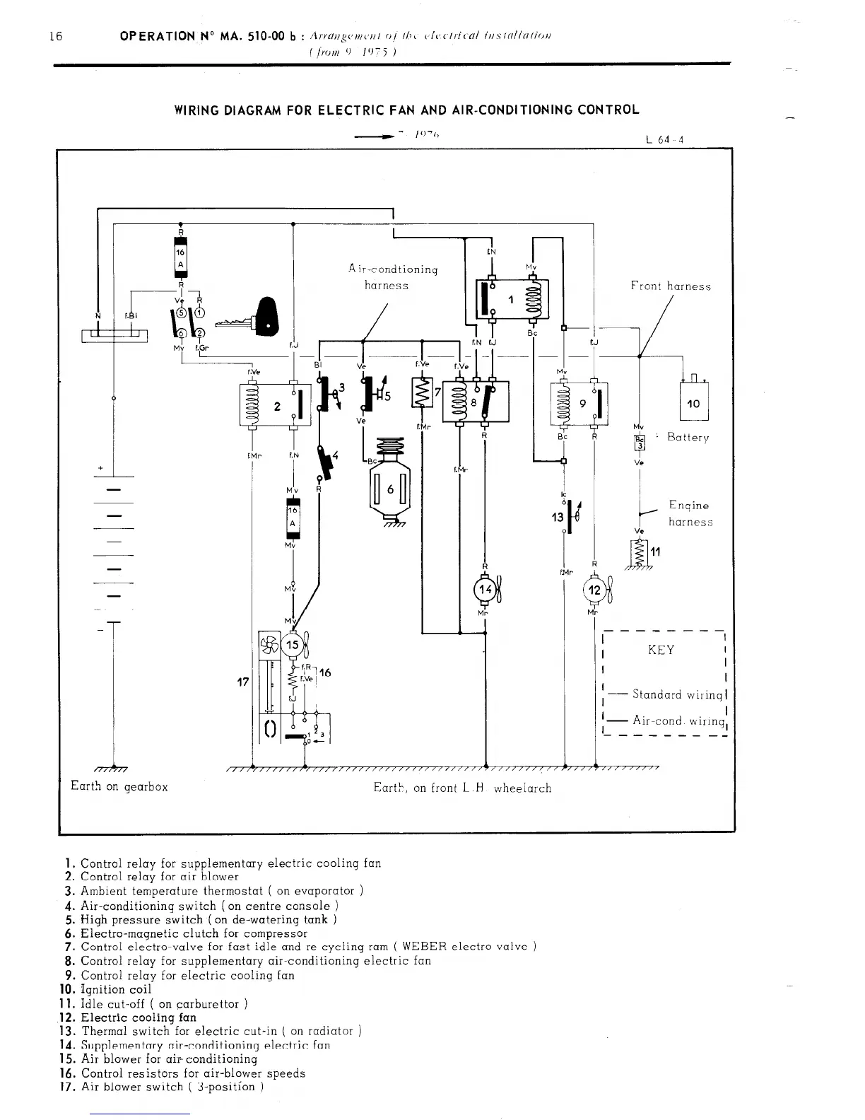
WIRING DIAGRAM FOR ELECTRIC FAN AND AIR-CONDITIONING CONTROL
--
I’)‘(,
L64 4
41 1 1 Front harness
-
T
17
I
KEY
I
I
I
I
Standard wiiinq
I
I
I
I I
I
- Air-cond wiIinq,
‘- - - - - - - _-
1
i 1
1
1
/,/r/////,/,,,,/,//////~////~‘/‘~””’~”””””~””7”“““’
Earth on gearbox
Eart>, on front L
H
wheelarch
1.
Control relay for supplementary electric cooling fan
2. Control relay for air blower
3. Ambient temperature thermostat ( on evaporator )
4. Air-conditioning switch (on centre console )
5. High pressure switch ( on de-watering tank )
6. Electra-magnetic clutch for compressor
7. Control electro-valve for fast idle and re-cycling ram
( WEBER electro-valve )
8. Control relay for supplementary air-conditioning electric
9. Control relay for electric cooling fan
10.
Ignition coil
11.
Idle cut-off ( on carburettor )
.12.
Electric cooling fan
13. Thermal switch for electric cut-in ( on radiator )
14. Supplementary air-conditioning electric fan
15. Air blower for air- conditioning
16.
Control resistors for air-blower speeds
17.
Air blower switch ( 3-position )