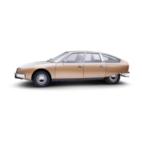
II. cx 2000
The object of the system is t3 reduce the amount of unburnt hydrocarbons and the amount of CO in the exhaust
( approximately 2 to 3
of CO ) by injectinq air under pressure into the exhaust manifold
OPERATION :
As the enqine rotates air pump ( 12) supplies the air injectors located near the exhaust valves: flap ( 13 )
prevents the exhaust fumes from entering the air pump and air supply duct assembly.
There are two cases where it is necessary to stop the injection of air into the exhaust manifold.
1. During deceleration :
\
Durinq fast deceleration. the mixture becomes richer combustion is incomplete and the injection of air is
stopped in order to avoid a second combustion takinq
place
in the exhaust system ( which would result in
back-firinq ) Durinq deceleration there is extreme low pressure downstream of the butterfly ( 1 ). This in
turn draws in for a short period of time the diaphragm in valve ( 11 )
The air supplied by pump ( 12 ) is released into the atmosphere, the calibrated hole (( a 1) on the diaphragm
balances the pressure on either side of it and the diaphraqm returns to its initial position, allowinq air to
be once more injected into the exhaust manifold
2. With the choke out, for an engine coolant temperature of above 45’ + 3’ C, and whenever the coolant tempe-
rature remains above 35’ i “,I C.
In this situation the quantities of unburnt hydrocarbons and CO are very considerable It ‘is therefore necessary
to stop the injection of air into the exhaust manifold so as to avoid any excessive increase of temperature in
the manifold. On CX 2000 vehicles, injkction of air will be stopped when the enqine water temperature reaches
45” + 3- C Thermal switch ( 8 ) opens, relay ( 9 )
1s no lonqer enerqized. but electro-valve ( 7 ) remains live
( relay lead ). and is earthed via the choke control
The air pressure at the outlet of air-pump ( 12 )
increases the effect of the low pressure on the diaphraqm in
valve ( 11 ) ( the air pressure is felt above the diaphraq,m, and the low pressure produced by the carburettor (2)
is felt below the diaphraqm ). the slidinq valve in the duct chanqes position and the air is expelled into the
atmogphere If the choke ( 10) is pushed back in air is once again injected into the exhaust manifold
DEVICE FOR OPENING THE BUTTERFLY :
The object of the device is to maintain combustion during sudden deceleration up to an enqine speed
of
Nd 7 1800 + 100 rpm.
Durinq deceleration for any enqine speed above
Nd,
the electronic tachometer housinq ( 6 ) earths the
windinq of relay ( 5) Therefore the H PIERBURG 1) electro-valve ( 4) is no lonqer enerqized. Electro-
valve ( 4) is then under low-pressure, below the diaphragm of the device ( 3 ) for opening the butterfly
When the decreasinq enqine speed falls below
Nd,
the electronic tachometer housing (6 ) cuts out the
earth of the winding in relay ( 5) Therefore the (( PIERBURG )) electro-valve ( 4) is enerqized The
electro-valve is no lonqer under low pressure below the diaphraqm of the device (3) for openinq the
butterfly the throttle butterfly returns to it
s stop aqainst the idlinq speed adjustment screw. The dia-
phraqm of the device (3) for openinq the butterfly will once aqain be affected by low pressure ( under
the control of the electronic tachometer housing ) once the increasing engine speed reaches
NC ~ Nd
t
50 to 250 rpm

 Loading...