ELECTRICAL
SYSTEM
12 72 A
90 A
280
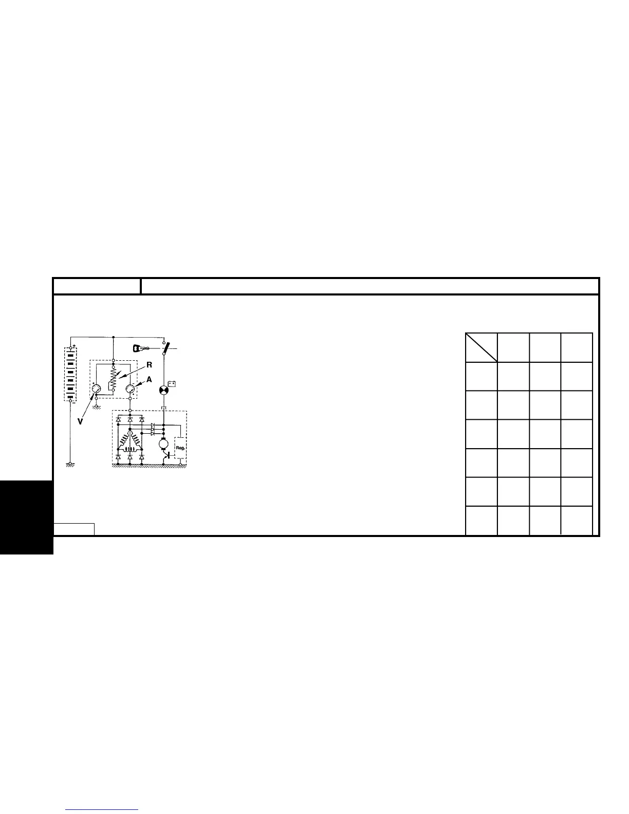
CHECKING THE ALTERNATOR OUTPUT
Connect as shown in the diagram opposite, using an ammeter (A), a
voltmeter (V) and a rheostat (R), or a Voltmeter/Ammeter/Rheostat
combination.
Adjust the engine speed (table opposite) and rheostat charge accor-
ding to the vehicle's equipment specification in order to obtain U = 13.5 V.
Reminder : The excitation energising current will flow through the
warning lamp - check that the warning lamp comes on when the igni-
tion is switched on. It must go out when the engine has started (acce-
lerate slightly).
CHECKING THE VOLTAGE REGULATOR
Set the rheostat to zero and disconnect all the electrical consu-
mers.Display 5000 alternator rpm. If U alternator is > 14.7 V, the regu-
lator is faulty.
Note : These tests should be performed with the engine hot and the
battery fully charged.
Speed
Class
2000
rpm
3000
rpm
4000
rpm
5
7
8
9
29 A
42 A
49 A
62 A
39 A
54 A
62 A
76 A
43 A
59 A
68 A
83 A
100 A
15 99 A
128 A
140 A
Output under 13.5 VCurrent (A) /
Alternator speed
CHARGING CIRCUIT - ALTERNATOR WITH MONO-FUNCTION REGULATOR
ALL TYPES
D1AP01SC

 Loading...