EasyManua.ls Logo

Clack WS 1 User Manual

Default Icon
21 pages
To Next Page IconTo Next Page
Page #1 background imageLoading...
Page #1 background image
Clack WS 1 water softener valve parts and operational manual
Bypass Valve
The bypass valve is typically used to isolate the control valve from the plumbing system’s water pressure
in order to perform control valve repairs or maintenance. The WS 1 bypass valve is particularly unique in
the water treatment industry due to its versatility and state of the art design features. The 1″ full flow
bypass valve incorporates four positions including a diagnostic position that allows service personal to
work on a pressurized system while still providing untreated bypass water to the facility or residence.
It’s completely non-metallic, all plastic design allows for easy access and serviceability without the need
for tools.
The bypass body and rotors are glass filled Noryl and the nuts and caps are glass filled polypropylene. All
seals are self-lubricating EPDM to help prevent valve seizing after long periods of non-use. Internal 0-
rings can easily be replaced if service is required.
The bypass consists of two interchangeable plug valves that are operated independently by red arrow
shaped handles. The handles identity the flow direction of the water. The plug valves enable the bypass
valve to operate in four positions.
Normal Operation Position: The inlet and outlet handles point in the direction of flow indicated by the
engraved arrows on the control valve. Water flows through the control valve during normal operation
and this position also allows the control valve to isolate the media bed during the regeneration cycle.
Question and Answer IconNeed help?

Do you have a question about the Clack WS 1 and is the answer not in the manual?

Clack WS 1 Specifications

General IconGeneral
ModelWS1
ManufacturerClack
Service Flow Rate27 gpm (6.1 m3/h)
Backwash Flow Rate27 gpm (6.1 m3/h)
Voltage12 VAC

Summary

Bypass Valve Operation

Normal Operation Position

Standard bypass valve state directing water through the control valve for normal use.

Bypass Position

Isolates control valve, allowing untreated water bypass for maintenance.

Diagnostic Position

Allows system pressure to control valve while bypassing to plumbing.

Shut Off Position

Stops water supply to plumbing, indicating potential system bypass.

Front Cover and Drive Assembly Parts

Drive Cap Assembly Components

Injector Assembly Components

Refill Port Plug Components

Drain Line Fittings and Components

Water Meter and Meter Plug Parts

Installation Fitting Assemblies

Service and Maintenance Procedures

Drive Assembly Servicing

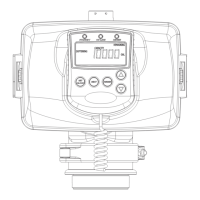
Instructions for removing and reinstalling the drive assembly and PC board.

Drive Cap and Piston Servicing

Procedures for servicing the drive cap, main piston, and regenerant piston.

Spacer Stack Assembly Servicing

Guidance on removing, cleaning, and reinstalling the spacer stack assembly.

Injector Component Servicing

Steps for cleaning and servicing the injector, screen, plug, and O-ring.

Refill Flow Control Servicing

Procedures for cleaning or replacing the refill flow control and retainer.

Water Meter Servicing

Instructions for inspecting, cleaning, and replacing the water meter assembly.

Bypass Valve Servicing

Detailed steps for servicing the bypass valve rotors and handles.

Troubleshooting Common Issues

Error Code Diagnostics

Resolves specific error codes by identifying causes and solutions.

Regeneration Stalling Issues

Diagnoses and resolves problems with the valve stalling during regeneration.

Automatic Regeneration Failures

Addresses causes and solutions for the valve not regenerating automatically.

Setup and Time Errors

Fixes issues related to setup errors and incorrect time of day settings.

Related product manuals