EasyManua.ls Logo

Clack WS1CI - User Manual

Default Icon
59 pages
Print Icon
To Next Page IconTo Next Page
Loading...
Water Specialist
1” Control Valve Series Model: WS1CI
1.25” Control Valve Series Model: WS1.25CI
Operation and Instruction Manual for OEM Only.
Please Note: This operation and instruction manual is for the training of the
OEM and for the OEM to use to train their customers. This document is not
to be used as the complete system manual.
TÜRK
SU ARAŞTIRMA
MERKEZİ
Turkish
Water
Association
Ayrıntılı Bilgi ve Sipariş için :
e-mail : bilgi@tusam.com.tr
web : www.tusam.com.tr
Phone : +90 850 302 0 392

Other manuals for Clack WS1CI

Question and Answer IconNeed help?

Do you have a question about the Clack WS1CI and is the answer not in the manual?

Clack WS1CI Specifications

General IconGeneral
ModelWS1CI
Valve MaterialNoryl
DisplayLCD
TypeControl Unit
Operating Pressure1.4 - 8.3 bar
Operating Temperature4°C - 43°C
Inlet/Outlet1" BSP
Drain Line1/2" BSP
Brine Line3/8" BSP
Riser Tube1.05 inch OD
Mounting Base2.5 inch - 8 NPSM
Power Supply12V AC, 50/60 Hz
TimerElectronic
Backup BatteryYes
Cycle SettingsAdjustable
CompatibilityWater Softeners

Summary

Introduction and Warnings

General Warnings

Lists essential warnings for OEM manuals regarding valve installation and usage.

Control Valve Function and Cycles

Valve Mechanical Components

Drive Assembly and Pistons

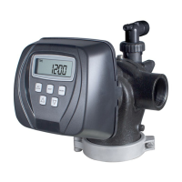
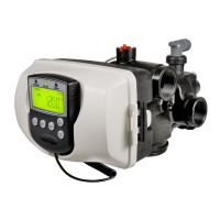
Explains the drive assembly, drive cap, pistons, and spacer stack.

Injector and Refill Systems

Injector System Components

Details the injector cap, screen, plug, and related components.

Drain Line Control

Water Meter, Mixing Valve, and Fittings

Bypass Valve Operation

Bypass Valve Positions

Explains the four operating positions of the bypass valve.

OEM Setup and Configuration

Cycle Sequence Configuration

OEM Softener System Setup

Guides OEMs through setting up softener cycles and parameters.

Filter System Setup

Diagnostics and History

Diagnostics

Details the diagnostic functions to check valve status and identify issues.

System Operation Modes

Time of Day and Salt Management

Adding Salt

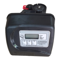
Instructions for monitoring salt levels and adding salt to the brine tank.

Installation Procedures

Drive Assembly Parts

Injector Parts

Injector Cap, Screen, Injector Plug and O-Ring

Exploded view and part list for injector components.

Bypass Valve Assembly

Bypass Valve Parts

Exploded view and part list for the bypass valve assembly.

Flow Diagrams: Service and Backwash

Service Flow Diagram

Illustrates water flow during the service cycle.

Flow Diagrams: Regeneration

Downflow Brine Flow Diagram

Illustrates water flow during the downflow brine regeneration cycle.

Flow Diagrams: Rinse and Fill

Service Instructions: Drive Assembly

Service Instructions: Drive Cap and Pistons

Service Instructions: Other Components

Troubleshooting Guide

Common Problems and Solutions

A table listing common problems, causes, and solutions.

Component Identification

Related product manuals