Introduction ..............................................................................................................................................................................................4
General Warnings (Must appear in OEM’s manual) ........................................................................................................................4
Specifi cations which must be included in OEM’s Manual ............................................................................................................... 5
Quick Reference Specifi cations ........................................................................................................................................................5
Control Valve Function and Cycles of Operation .................................................................................................................................... 6
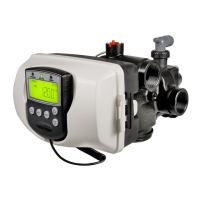
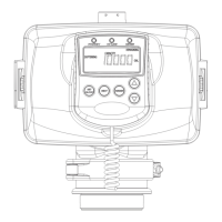
Drive Assembly ................................................................................................................................................................................8
Drive Cap Assembly, Main Piston and Regenerant Piston ...............................................................................................................8
Spacer Stack Assembly ..................................................................................................................................................................... 8
Injector Cap, Screen, Injector Plug and Injector ...............................................................................................................................9
Refi ll Flow Control Assembly or Refi ll Port Plug ............................................................................................................................9
Drain Line Flow Control and Fitting Assembly ............................................................................................................................. 10
Water Meter or Meter Plug ............................................................................................................................................................. 11
Mixing Valve .................................................................................................................................................................................. 11
Installation Fitting Assemblies ....................................................................................................................................................... 11
Bypass Valve ...................................................................................................................................................................................12
OEM General Instructions .....................................................................................................................................................................14
OEM Cycle Sequence .....................................................................................................................................................................15
OEM Softener System Setup .........................................................................................................................................................16
OEM Filter System Setup .............................................................................................................................................................. 19
Installer Display Settings ................................................................................................................................................................21
User Display Settings .....................................................................................................................................................................22
Diagnostics .....................................................................................................................................................................................25
Valve History .................................................................................................................................................................................. 26
Installation ..............................................................................................................................................................................................27
Drawings and Part Numbers .................................................................................................................................................................. 29
Front Cover and Drive Assembly ................................................................................................................................................... 30
WS1CI Drive Cap Assembly, Downfl ow Piston, Upfl ow Piston, Regenerant Piston and Spacer Stack Assembly .......................31
WS1.25CI Drive Cap Assembly, Downfl ow Piston, Upfl ow Piston, Regenerant Piston and Spacer Stack Assembly ..................32
Injector Cap, Injector Screen, Injector, Plug and O-ring ................................................................................................................33
Refi ll Flow Control Assembly and Refi ll Port Plug ........................................................................................................................34
Drain Line – 3/4” ............................................................................................................................................................................35
Drain Line – 1” ...............................................................................................................................................................................36
Water Meter, Meter Plug and Mixing Valve ...................................................................................................................................37
Installation Fitting Assemblies .......................................................................................................................................................38
Bypass Valve ...................................................................................................................................................................................40
Flow Diagrams – Service and Backwash .......................................................................................................................................41
Flow Diagrams – Downfl ow and Upfl ow Brine ............................................................................................................................. 42
Flow Diagrams – Rinse and Fill .....................................................................................................................................................43
WS1 Wrench .................................................................................................................................................................................. 44
Service Instructions ................................................................................................................................................................................ 45
Troubleshooting .....................................................................................................................................................................................50
WS1CI & WS1.25CI Identifi cation ....................................................................................................................................................... 52
Injector Graphs US Units: Injector Draw, Slow Rinse and Total Flow Rates .......................................................................................53
Injector Graphs Metric Units: Injector Draw, Slow Rinse and Total Flow Rates ..................................................................................55
Limited Warranty ...................................................................................................................................................................................60
Table of Contents