Do you have a question about the Clack WS CI Series and is the answer not in the manual?
Checks for level area, frost-free conditions, electricity, open drain, water quality, pressure, and temperature.
Instructions on fitting the bottom distribution system into the vessel.
Guidance on adding water and media to the vessel, leaving space for backwashing.
Steps for greasing valve o-rings and attaching the valve to the riser tube.
Instructions for attaching brine line tubing to the brine tank and valve.
Connecting pipework to inlet/outlet connections using supplied tails or direct BSP threads.
Importance and fitting of the drain line flow control for backwash rate.
Checking the injector is fitted correctly in the DN position with the UP position plugged.
Steps for connecting the power cable to the PCB board and drive bracket.
Overview of quick start and programming the valves.
Instructions for setting time of day, hardness, nitrate, and colour settings.
Steps to reset valve programming after memory loss, including cycle sequence and system setup.
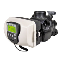
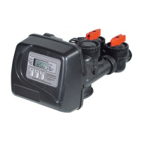
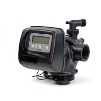
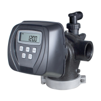
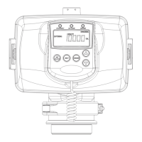
How to read the identification label on the control valve to identify the system type.
Sequence for applying settings for Softener setup, including cycle sequence and system setup.
Settings sequence for CR100 Crystal-Right, including cycle sequence and system setup.
Settings sequence for CR200 Crystal-Right, including cycle sequence and system setup.
Settings for Nitrate Removal setup, including cycle sequence and system setup.
Settings for Colour Removal setup, including cycle sequence and system setup.
Settings for AquaMulti setup, including cycle sequence and system setup.
Details about valve functions, options, and settings for Cl valves.
Introduction to the commissioning process after system installation and programming.
How to perform manual regeneration for commissioning, bedding resin, and flushing.
Explanation of the service mode and how water flows through the system.
Checks to perform weekly, including salt level, leaks, and water quality.
Checks to perform monthly, focusing on incoming water quality changes.
Checks to perform yearly, primarily for leaks or damage.
Guidelines for using Soda Ash as a regenerant for Crystal-Right installations.
Addresses issues related to the PC board display and power.
Solutions for incorrect time display on the PC board, possibly due to power interruptions.
Troubleshooting steps when the display doesn't show water flow, referring to user instructions.
Explains causes and solutions for the control valve regenerating at incorrect times.
Addresses the issue of the time of day display flashing, often related to power.
Solutions when the control valve fails to initiate regeneration automatically.
Troubleshooting when regeneration only occurs manually, not automatically.
Problems and solutions when hard or untreated water is supplied to the system.
Investigating and resolving issues related to excessive regenerant consumption.
Diagnosing and fixing problems where residual regenerant is present in the service water.
Identifying causes and solutions for excessive water accumulation in the regenerant tank.
Troubleshooting steps when the control valve is unable to draw regenerant from the tank.
Addresses issues of water continuously running to the drain, potentially during regeneration or other cycles.
Solutions for error codes indicating the control valve cannot sense motor movement.
Troubleshooting error codes related to the motor running too short and stalling.
Solutions for error codes indicating the motor ran too long without finding the next cycle position.
Troubleshooting error codes for motor over-running and timing out while reaching the home position.
Solutions for errors related to MAV/SEPS/NHBP/AUX MAV valve motor over-running and failing to park.
Troubleshooting error codes for MAV/SEPS/NHBP/AUX MAV valve motor stalling while seeking park position.
| Brand | Clack |
|---|---|
| Model | WS CI Series |
| Category | Control Unit |
| Language | English |