6
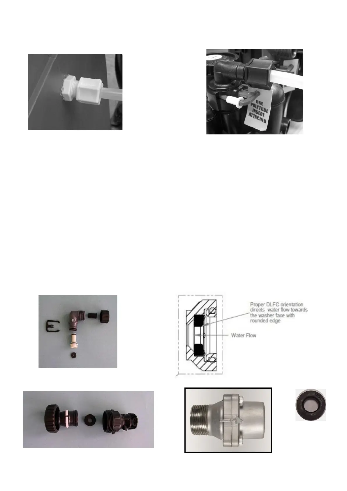
2.5 Brine Tank Connections.
Attach the brine line tubing to the brine tank and valve using the connectors fitted to the brine
tank (fig A.7), and valve (fig A.8).
Fig A.7 Fig A.8
Sizes may vary depending on the valve used, please note to use the poly insert if provided
with your specific valve.
2.6 Hydraulic Connections.
Connect your pipe work to the inlet / outlet connections; use the supplied tails provided for 1”
and 1.25” valves or direct BSP threaded connections on the 1.5” or 2” valves.
2.7 DLFC (drain line flow control)
This is possibly one of the most important components to check has been installed; this will
control the backwash flow rate and ensure the system will continue to function correctly. The
DLFC will either be fitted inside the drain line elbow, the 1” adaptor or in an external housing.
The larger external DLFC may have more than one flow controls fitted to gain the required
flow rate. See below pictures of the drain line housings.
¾” Elbow
Insert
1” External Straight 1.½” External
 Loading...