7
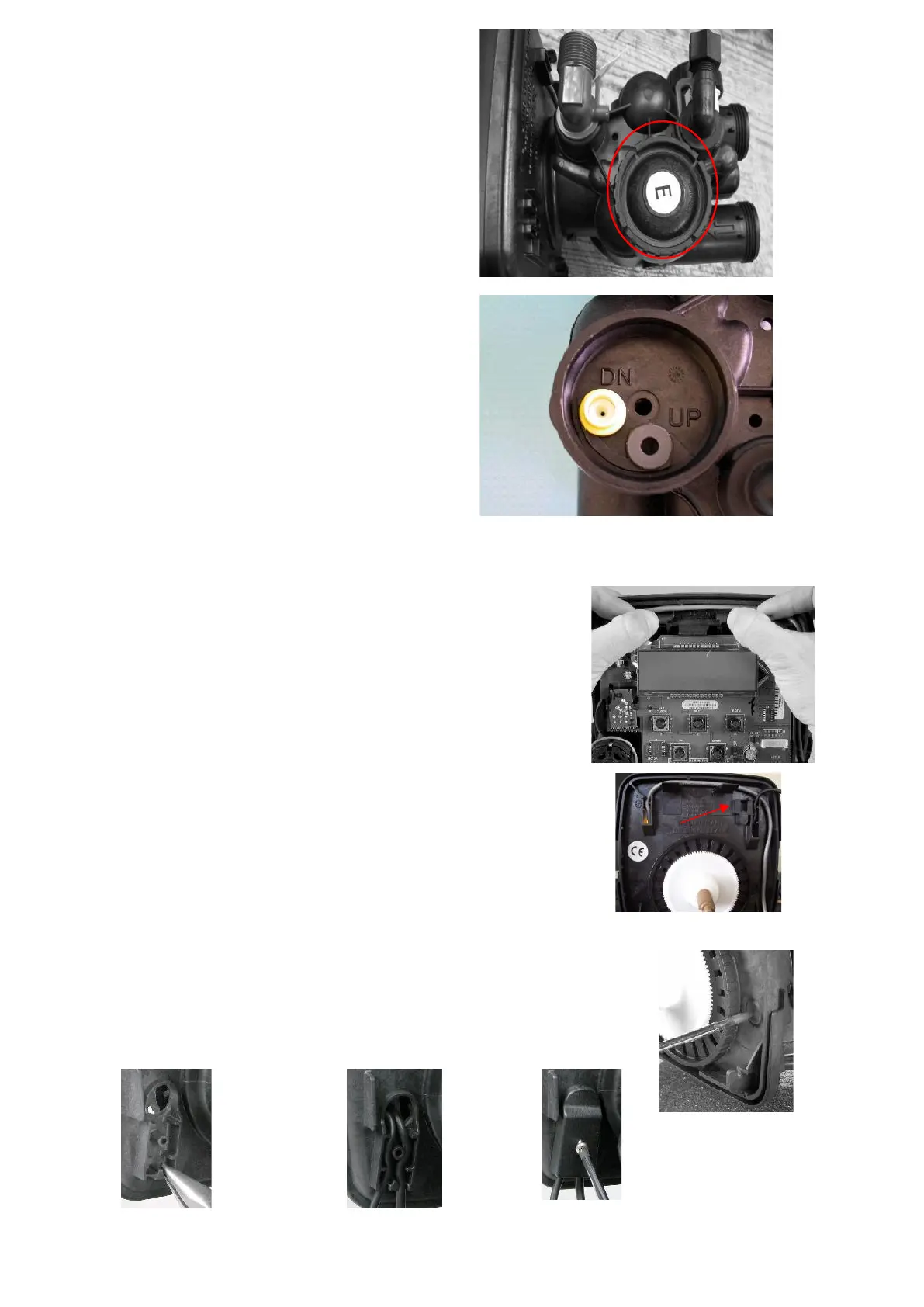
2.8 Injector
The injector is another important item in the
functioning of the system, please check that
it is fitted in the DN position and that the UP
position has been plugged. The injector colour
will vary depending on the size of the system,
this should be listed on the items list.
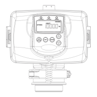
2.9 Electrical connections
To connect the power cable you need to firstly remove the
cover then remove the drive bracket assembly by pressing
up on the drive brackets release tabs and pulling towards
you, the drive bracket including software can now be lifted
away to reveal the back plate (fig A.9).
Fig A.9
The power cable should be threaded through the back plate
And strain relief as shown in Fig A.9a
Fig A.9a
You can now re install the drive bracket into its original position.
Please make sure that this has been replaced correctly as this can cause problems at a
later date.
If fitting a MAV or NHBP locate the knock out on the back plate
Fig A.10 then remove the tabs at the bottom of the strain relief
on the back side of the back plate fig A.11 thread the cables
Fig A.12 and fit the cover Fig A13
Fig A.10
Fig A.11 Fig A.12 Fig A.13
 Loading...