4
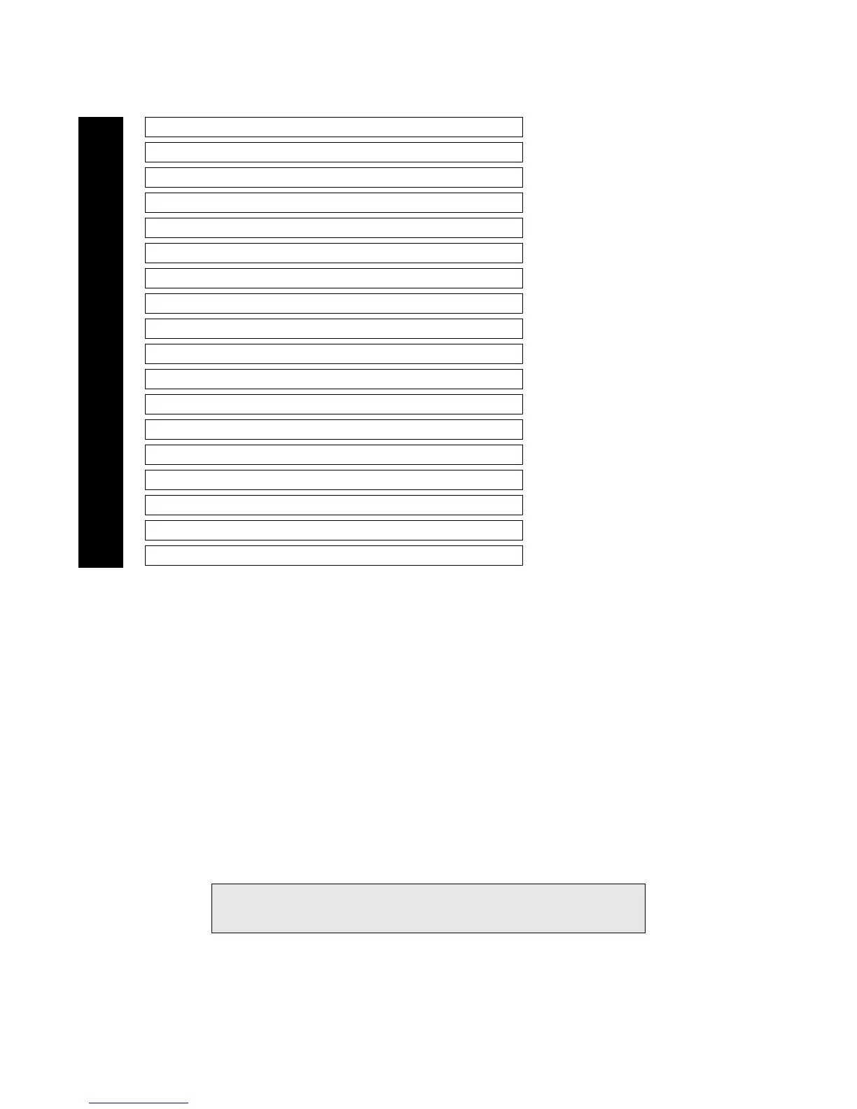
Primary Harness (H1), 18-pin connector
___
___
___
___
___
___
___
___
___
___
___
___
___
___
___
___
___
___
H1/1 RED (+)12V Constant Power Input
Before connecting this wire, remove the supplied fuse. Connect to the battery positive terminal or the constant 12V supply to the ignition switch.
NOTE: Always use a fuse within 12 inches of the point you obtain (+)12V. Do not use the fuse in the harness for this purpose. This fuse pro-
tects the module itself.
H1/2 BLUE (-) 200 mA Second Unlock Output
The H1/2 BLUE output is used for progressive unlock. A progressive unlock system unlocks the driver's door when the unlock (disarm) button
is pressed and unlocks the passenger doors if the unlock (disarm) button is pressed again within 15 seconds after unlocking the driver's door. The
BLUE wire outputs a low current (-) pulse on the second press of the unlock button of the transmitter. This negative unlock output is used to
unlock the passenger doors.
H1/3 BLACK/WHITE-1 Domelight Supervision Input
This wire determines what the output polarity of H1/4 will be. If the door pin circuit is negative, connect to chassis ground. If the door circuit
is positive, connect to a fused 12V source.
H1/4 BLACK/WHITE Domelight Supervision Output
Connect this wire directly to the domelight circuit in the vehicle. The on-board relay will drive circuits up to 30 amperes. The polarity of this
output is determined by the connection of the input wire H1/3 in the Relay Harness.
NOTE: If the input wire H1/3 is not connected, there will be no output on this wire.
IMPORTANT! The H1/3 wire is not required for wiring the door locks. Depending on
the type of door lock system, there may be additional wires for the Door Lock wiring
that are not required.
RED/WHITE (-) OUTPUT OF CHANNEL 2
BROWN/BLACK UNLOCK #87A NORMALLY CLOSED
ORANGE (-) 500 mA GROUND-WHEN-ARMED OUTPUT
YELLOW (+) SWITCHED IGNITION INPUT (ACCESSORY)
WHITE/BLUE (-) 200 mA CHANNEL 3 VALIDITY OUTPUT
LT. GREEN/BLACK FACTORY ALARM DISARM
BROWN (-) HORN HONK OUTPUT
BLACK (-) CHASSIS GROUND INPUT
WHITE (+/-) PARKING LIGHT FLASH OUTPUT
VIOLET UNLOCK #87 NORMALLY OPEN (INPUT)
BLUE/BLACK UNLOCK #30 COMMON (OUTPUT)
VIOLET/BLACK LOCK #87 NORMALLY OPEN (INPUT)
WHITE/BLACK LOCK #87 NORMALLY CLOSED
GREEN/BLACK LOCK #30 COMMON OUTPUT
BLACK/WHITE OUTPUT OF DOMELIGHT SUPERVISION RELAY #30
BLACK/WHITE-1 INPUT OF DOMELIGHT SUPERVISION RELAY #87
BLUE (-) 200 mA SECOND UNLOCK OUTPUT
RED (+) 12V CONSTANT POWER INPUT
H1/1
H1/2
H1/3
H1/4
H1/5
H1/6
H1/7
H1/8
H1/9
H1/10
H1/11
H1/12
H1/13
H1/14
H1/15
H1/16
H1/17
H1/18