EF-701M INTERFACE 1-11
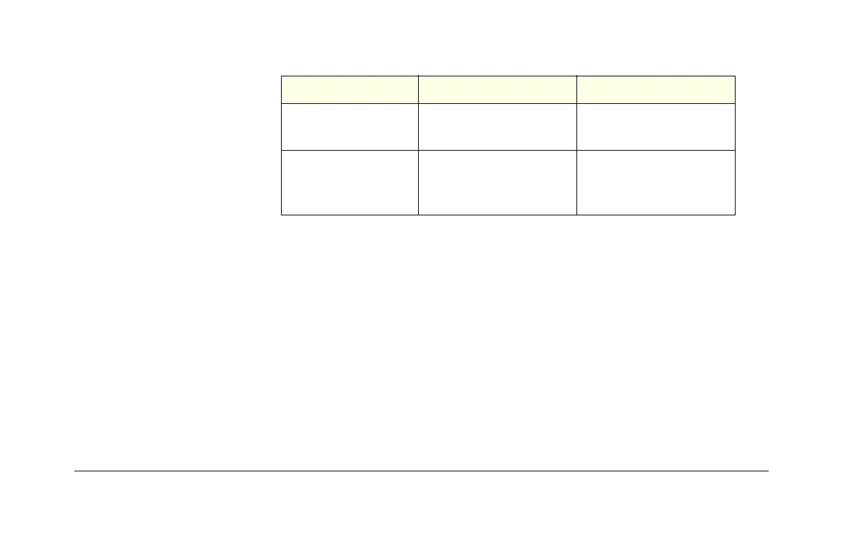
Table 1-1: EF-701M’s mode-switch settings
3-Pin XLR Connector (Party Line I/O)
The female 3-pin XLR jack on the EF-701M’s back panel connects to the 2-wire party
line. If a loop-through connection is needed, use a high quality “Y” cable like the
Clear-Com SP-3.
Note: Each (local) party-line channel must have one, but only one, termination.
MODE SWITCH OFF (DEFAULT) ON
MODE-SWITCH 1
RJ-45 connects to
4-Wire/Fiber
RJ-45 connects to
Matrix directly
MODE-SWITCH 2
DB-15 sends/receives
C-C DC Call, C-C
Intercom Level
DB-15 sends/receives
20-kHz Call, RTS-TW
Intercom Level