EF-701M INTERFACE 2-3
The four pairs of cable used for full operation include one each for audio in and audio out
and one each for RS-422 data in and data out.
Take care to wire the DB-15 or RJ-45 pins correctly. For added reference Figure 2-1
shows the pinout configuration. A stick-on label with the pinout assignments has been
included for the user’s convenience. Attach this in a convenient location.
After wiring the DB-15 to the appropriate connectors, follow these steps to connect the
EF-701M to a modem:
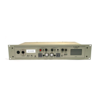
1. Connect the local party-line channel to the EF-701M’s rear-panel 3-pin XLR
connector.
2.Check to see that the EF-701M is receiving power by checking the green Power LED
(the “on” light). If there is a powered EF-701M properly connected at the other end of
the transmission line, the amber Data LED should also illuminate within a second or
two. This confirms a proper data “handshake” between the two units.
3.Send a call signal and check that it is received at the distant intercom system.
4.Adjust nulls, and then check audio levels as required.
5.Repeat as necessary for each EF-701M in the system.