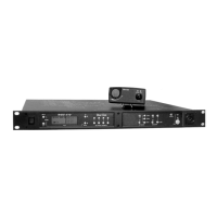
Con trols and Con nec tions - Rear Panel
Fig ure 8
WTR-682 Rear Panel/Con nec tor/An tennas
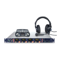
1. [MENU] and [SET] but tons – Used to se lect menus and
set op tions on the LCD.
2. LCD (Liq uid Crys tal Dis play)
3. [UP] and [DOWN] but tons – Used to se lect beltpack op -
tions on the LCD.
4. Mi cro phone Gain – Ad justs the head set’s mi cro phone
gain. Ad just so that the BAT/OM LED will flash at the be -
gin ning of most words at nor mal speech lev els.
5. Push-to-Talk/Push-to-Transmit Switch –
Push-to-Talk (PT TALK) – The trans mit ter is al ways
on. No au dio sent un less the talk switch, WTA or SA
but ton pressed. Rec om mended po si tion.
Push-to-Transmit (PT TX) - The trans mit ter and au -
dio path are off ex cept when the talk switch, WTA or
SA but ton is pressed.
Fig ure 9
Head set Jack Wiring
6. Head set Con nec tor – Male XLR con nec tor. A dy namic or
electret head set mi cro phone is au to mat i cally de tected by
the beltpack and a bias volt age sup plied if needed.
7. Bat tery Latch – Press down to en able the bat tery pack to
be re leased. While the latch is held down, slide the bat tery
pack about 1/8 inch back, to ward latch, un til it stops. Then
lift out.
8. Re ceive An tenna – Screw type ¼-wave re place able an -
tenna. The color dot on the screw end of the an tenna must
match color dot on an tenna re cep ta cle.
9. Trans mit An tenna – Screw type ¼-wave re place able an -
tenna. The color dot on the screw end of the an tenna must
match color dot on an tenna re cep ta cle.
4-2
MENU
SET
M
I
C
P
T
T
X
P
T
T
A
L
K
6
6
7
7
8
8
9
9
MENU
SET
M
IC
PT
T
X
PT
TA
L
K
2
2
1
1
3
3
4
4
5
5
(1) Microphone
Shield (-)
(2) Microphone
Audio (+)
(4) Headphone
Low (-)
(3) Headphone
High (+)