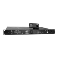
Con trols and Con nec tions - Rear Panel
Fig ure 5
WTR-680 Rear Panel/Con nec tor/An tennas
1. [MENU] and [SET] but tons – Used to se lect menus and
set op tions on the LCD.
2. LCD (Liq uid Crys tal Dis play)
3. [UP] and [DOWN] but tons – Used to se lect beltpack op -
tions on the LCD.
4. Mi cro phone Gain – Ad justs the head set’s mi cro phone
gain. Ad just so that the BAT/OM LED will flash at the be -
gin ning of most words at nor mal speech lev els.
5. Push-to-Talk/Push-to-Transmit Switch –
Push-to-Talk (PT TALK) – The trans mit ter is al ways
on. No au dio sent un less the talk switch, WTA or SA
but ton pressed. Rec om mended po si tion.
Push-to-Transmit (PT TX) - The trans mit ter and au -
dio path are off ex cept when the talk switch, WTA or
SA but ton is pressed.
Fig ure 6
Head set Jack Wiring
6. Head set Con nec tor – Male XLR con nec tor. A dy namic or
electret head set mi cro phone is au to mat i cally de tected by
the beltpack and a bias volt age sup plied if needed.
7. Bat tery Latch – Press down to en able the bat tery pack to
be re leased. While the latch is held down, slide the bat tery
pack about 1/8 inch back, to ward the latch, un til it stops.
Then lift out.
8. Re ceive An tenna – Screw type ¼-wave re place able an -
tenna. The re ceiver an tenna is al ways the lon ger an tenna.
Color dot on the screw end of the an tenna must match
color dot on an tenna re cep ta cle.
9. Trans mit An tenna – Screw type ¼-wave re place able an -
tenna. Color dot on the screw end of the an tenna must
match color dot on an tenna re cep ta cle.
3-2
MENU
SET
M
I
C
P
T
T
X
PT
T
A
LK
6
7
8
9
MENU
SET
M
I
C
P
T
TX
PT
T
AL
K
2
1
3
4
5
(1) Microphone
Shield (-)
(2) Microphone
Audio (+)
(4) Headphone
Low (-)
(3) Headphone
High (+)