CB FALCON MODBUS COMMUNICATION
28
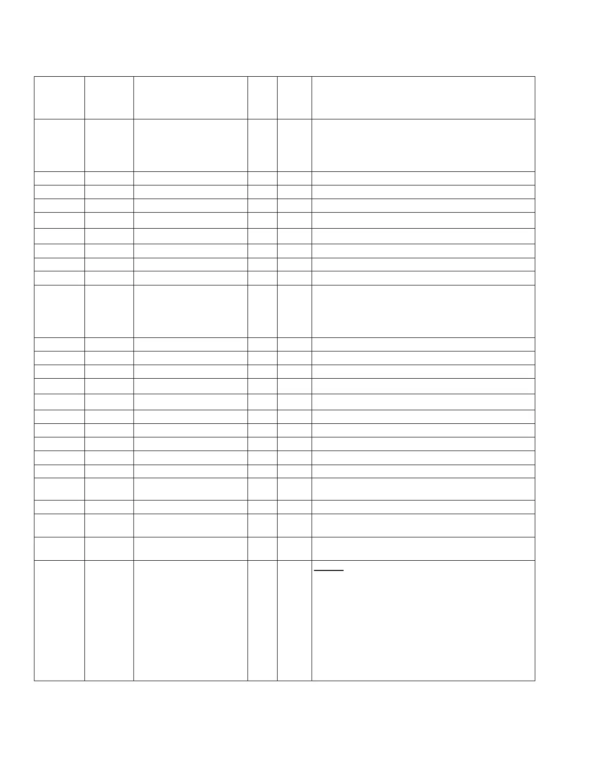
Table 4. CB Falcon Modbus register map
02C9 0713
Slave dropout/return
compensation
R/W U16 0=No slave compensation,
1=Replace dropout immediately,
2=Adjust rate for remaining slaves,
3=Both replace dropout & adjust rate
02CA 0714 Add stage method R/W U16 0=Do not add stage,
1=Use error threshold,
2=Use firing rate threshold,
3=Use error rate change & threshold,
4=Use firing rate change & threshold
02CB 0715 RESERVED
02CC 0716 Add stage detection time R/W U16 0-64800 seconds (18 hours), 0xFFFF=Not configured
02CD 0717 RESERVED
02CE 0718 Add stage error threshold R/W U16
0°-130° (0.1°C precision)
a
02CF 0719 Add stage rate offset R/W U16
-100-100%
2
(0.1% units)
02D0 0720 Add stage error gain R/W U16 0-100
02D1 0721 Add stage rate gain R/W U16 0-100
02D2 0722 Add stage inter-stage delay R/W U16 0-64800 seconds (18 hours), 0xFFFF=Not configured
02D3 0723 Drop stage method R/W U16 0=Do not drop stage,
1=Use error threshold,
2=Use firing rate threshold,
3=Use error rate change & threshold,
4=Use firing rate change & threshold
02D4 0724 RESERVED
02D5 0725 Drop stage detection time R/W U16 0-64800 seconds (18 hours), 0xFFFF=Not configured
02D6 0726 RESERVED
02D7 0727 Drop stage error threshold R/W U16
0°-130° (0.1°C precision)
a
02D8 0728 Drop stage rate offset R/W U16
-100-100%
2
(0.1% units)
02D9 0729 Drop stage error gain R/W U16 0-100
02DA 0730 Drop stage rate gain R/W U16 0-100
02DB 0731 Drop stage inter-stage delay R/W U16 0-64800 seconds (18 hours), 0xFFFF=Not configured
02DC 0732 RESERVED
02DD 0733 Lead rotation time R/W U16 0-64800 minutes (1080 hours), 0xFFFF=Not configured
02DE 0734 Force lead rotation time R/W U16 0-64800 minutes (1080 hours), 0xFFFF=Not configured
02DF-02EF 0735-0751 RESERVED
EXTENDED PUMP
CONFIGURATION
02F0 0752
Auxiliary 1 pump overrun
time
R/W U16 0-64800 seconds (18 hours), 0xFFFF=Not configured
02F1 0753 Auxiliary 1 pump options 1 R/W U16 Bit map:
15=Normal pump demand when auxiliary pump Z is set,
14=Normal pump demand when auxiliary pump Y is set,
13=Normal pump demand when auxiliary pump X is set,
12-7=Reserved (always 0),
6=Normal pump demand when DHW service is active,
5=Normal pump demand when CH service is active,
4=Reserved,
3=Normal pump demand when DHW demand,
2=Normal pump demand when CH demand,
1=Normal pump demand when local burner demand,
0=Local demand inhibited for faults