CB FALCON MODBUS COMMUNICATION
29
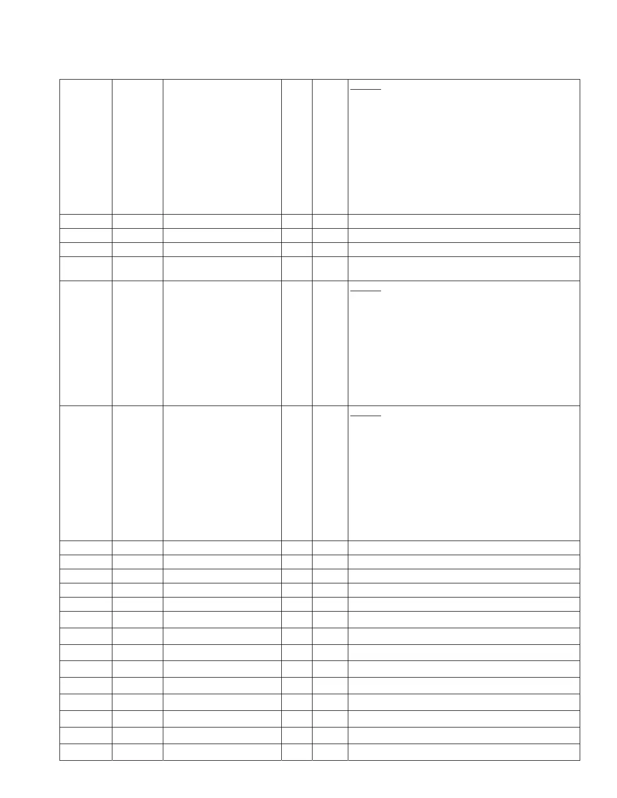
Table 4. CB Falcon Modbus register map
02F2 0754 Auxiliary 1 pump options 2 R/W U16 Bit map:
15=Pump used for Lead Lag,
14=Pump used for local demand,
13-9=Reserved (always 0),
8=Force pump off when DHW high limit,
7=Force pump off when DHW anti-condensation,
6=Force pump off when CH anti-condensation,
5=Force pump off when DHW priority is active,
4=Force pump on when DHW frost protection,
3=Force pump on when CH frost protection,
2=Force pump on when Lead Lag slave demand,
1=Force pump on when local burner demand,
0=Force pump on when Outlet high limit
02F3 0755 Auxiliary 2 pump output R/W U16 0=None, 1=Pump A, 2=Pump B, 3=Pump C
02F4 0756 Auxiliary 2 pump control R/W U16 0=Auto, 1=On
02F5 0757 Auxiliary 2 pump start delay R/W U16 0-64800 seconds (18 hours), 0xFFFF=Not configured
02F6 0758
Auxiliary 2 pump overrun
time
R/W U16 0-64800 seconds (18 hours), 0xFFFF=Not configured
02F7 0759 Auxiliary 2 pump options 1 R/W U16 Bit map:
15=Normal pump demand when auxiliary pump Z is set,
14=Normal pump demand when auxiliary pump Y is set,
13=Normal pump demand when auxiliary pump X is set,
12-7=Reserved (always 0),
6=Normal pump demand when DHW service is active,
5=Normal pump demand when CH service is active,
4=Reserved,
3=Normal pump demand when DHW demand,
2=Normal pump demand when CH demand,
1=Normal pump demand when local burner demand,
0=Local demand inhibited for faults
02F8 07600760 Auxiliary 2 pump options 2 R/W U16 Bit map:
15=Pump used for Lead Lag,
14=Pump used for local demand,
13-9=Reserved (always 0),
8=Force pump off when DHW high limit,
7=Force pump off when DHW anti-condensation,
6=Force pump off when CH anti-condensation,
5=Force pump off when DHW priority is active,
4=Force pump on when DHW frost protection,
3=Force pump on when CH frost protection,
2=Force pump on when Lead Lag slave demand,
1=Force pump on when local burner demand,
0=Force pump on when Outlet high limit
02F9-033F 0761-0831 RESERVED
SAFETY CONFIGURATION
0340-035F 0832-0863 RESERVED
LOCKOUT HISTORY
0360-0370 0864-0880 Lockout history record 1 R Most recent lockout. See Table 5.
0371-0381 0881-0897 Lockout history record 2 R
2
nd
newest lockout. See Table 5.
0382-0392 0898-0914 Lockout history record 3 R
3
rd
newest lockout. See Table 5.
0393-03A3 0915-0931 Lockout history record 4 R
4
th
newest lockout. See Table 5.
03A4-03B4 0932-0948 Lockout history record 5 R
5
th
newest lockout. See Table 5.
03B5-03C5 0949-0965 Lockout history record 6 R
6
th
newest lockout. See Table 5.
03C6-03D6 0966-0982 Lockout history record 7 R
7
th
newest lockout. See Table 5.
03D7-03E7 0983-0999 Lockout history record 8 R
8
th
newest lockout. See Table 5.
03E8-03F8 1000-1016 Lockout history record 9 R
9
th
newest lockout. See Table 5.
03F9-0409 1017-1033 Lockout history record 10 R
10
th
newest lockout. See Table 5.