14.18
1.00WITHIN
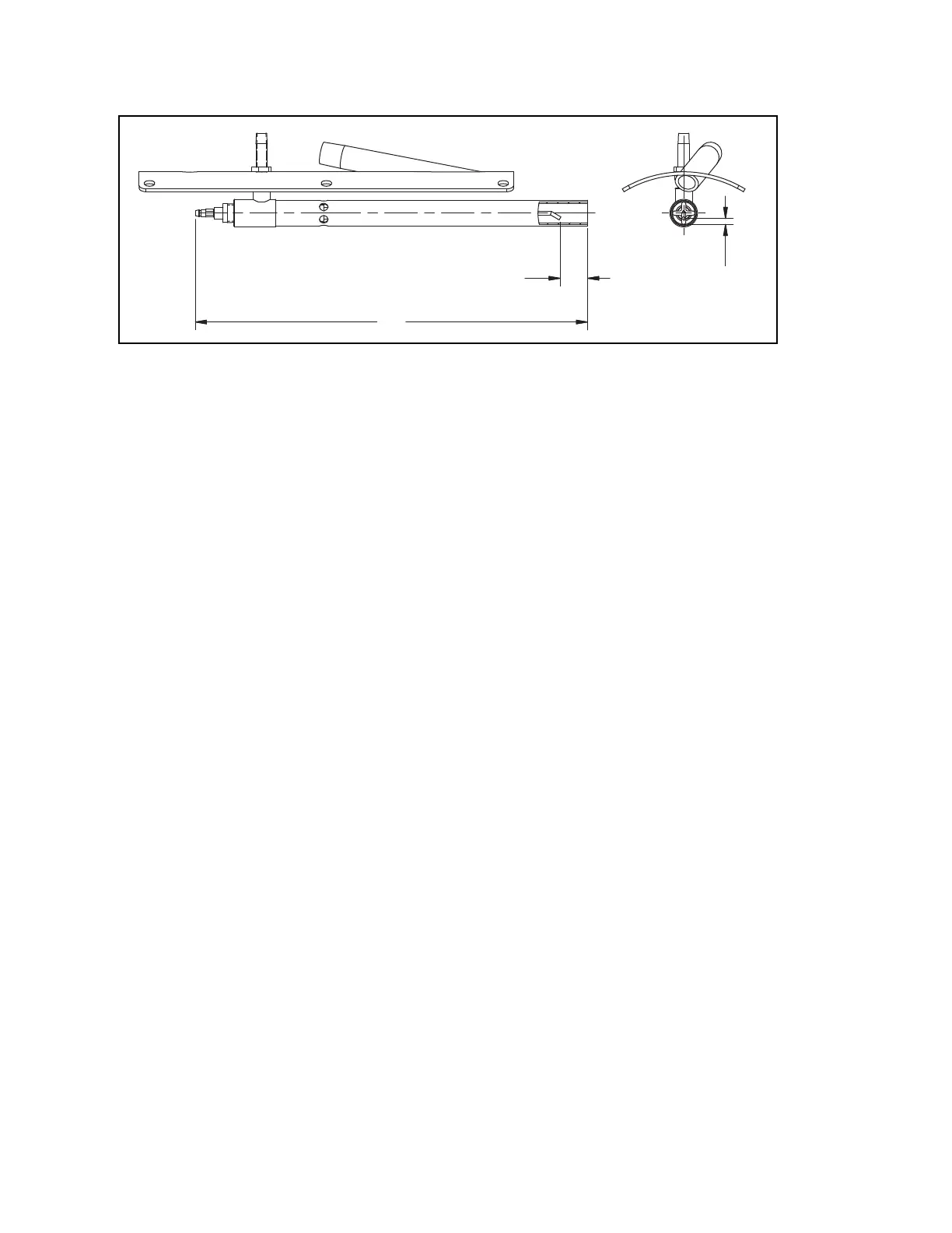
ELECTRODE END
"
TUBE END
TIP TO TUBE
GAP OF .16"
Chapter 2 Profire V Burner
2-28 750-177
Figure 2-13: Direct Spark Ignition- Oil Only
BURNER PILOT SETTINGS
To ensure reliable and safe burner performance, the location and gap setting of
the electrodes, and the relative
positions of the burner nozzle, diffuser, and air baffle components must be set correctly. These items are preset
at the factory, but must be checked prior to placing the burner into initial service, or after conducting any
service work that may have altered their position.
The nozzle/diffuser assembly must be removed
from inside the burner to enable measurement and
readjustment:
1. Lock out and tag the electrical power supply to the burner to prevent inadvertent operation during checkout or
maintenance activities.
2. Disconnect the high voltage power supply from th
e oil-spark-ignition electrodes (if installed).
3. Disconnect the oil piping from the side of the blast tube.
4. Remove the fasteners that secure the drawer to the side of
the burner housing, and remove the complete assembly.
For burners with a gas pilot:
1. Disconnect the pilot line and loosen the locking screws on the pilot access cover located on the side of the blast
tube.
2. Disconnect the high voltage ignition cable by pulling it straight back, away from the pilot assembly. The pilot
ass
embly will slide back away from the diffuser.
3. Turn the assembly and retract it through the access hole.
4. Check the electrode position.
5. Re-assemble in reverse order.
 Loading...


