14.18
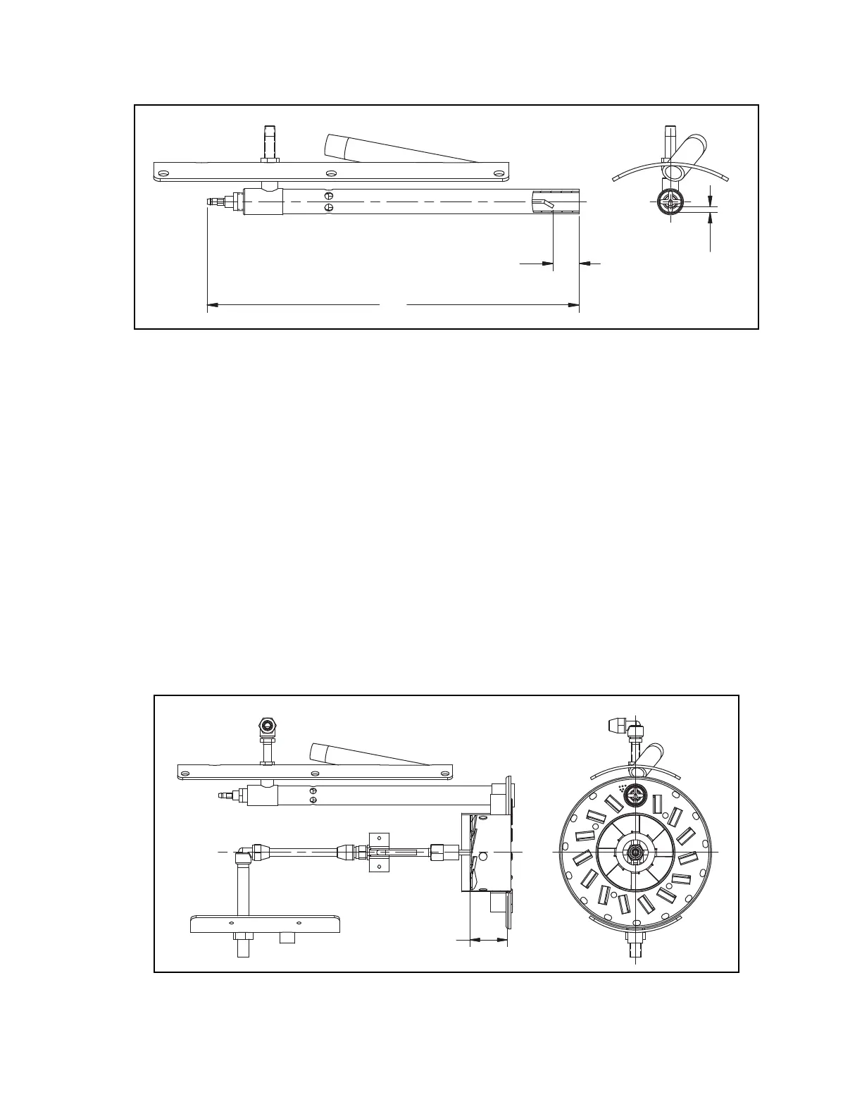
1.00WITHIN
ELECTRODE END
"
TUBE END
TIP TO TUBE
GAP OF .16"
Profire V Burner Chapter 2
750-177 2-29
Figure 2-14: Gas Pilot
Measure the position of the tip of the nozzle to the diffuser and compare to the following drawer assembly
drawings. To adjust:
1. Loosen the locking screws on the diffuser clamp.
2. Slide the diffuser clamp along the length of the burner pipe un
til the correct dimension is achieved.
3. Tighten the diffuser clamp securely to the burner pipe. Apply a loc
k-tight type compound to the screws before tight-
ening.
4. Carefully install the drawer assembly into the burner.
5. Re-connect the oil line and high voltage power cable to the assembly.
Measure the position of the diffuser to the air baffle and compare to the following drawer assembly drawings.
To adjust:
1. Measure the distance between the leading edge of the diffuser and the front face of the inner ring on the air baffle
assembly.
2. If adjustment is required, loosen the burner pipe locking se
tscrew located on the rear cap at the top of the fan hous-
ing, and slide the burner pipe until the correct dimen
sion is achieved.
3. Tighten the burner pipe locking setscrew securely.
1.83" REAR FACE
OF DIFFUSER TO
FRONT FACE OF
AIR BAFFLE
Figure 2-15: Drawer Assembly for (VG) Gas Only (V13-34) - Watertube/
 Loading...


