GENERAL DESCRIPTION Chapter 1
750-177 1-5
stop or start the burner at a preselected operating
temperature.
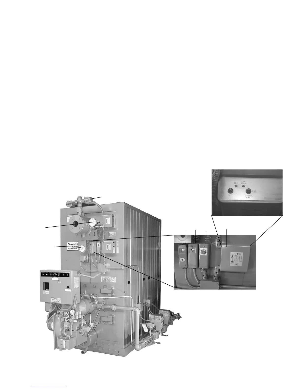
4. High Limit Temperature Control (Figure 1-7): Breaks a
circuit to stop burner operation on a rise of temperature
at a selected setting. It is adjusted to stop burner at a
preselected temperature above the operating control
setting. The high limit temperature control is equipped
with a manual reset.
5. Modulating Temperature Control (Figure 1-7): Senses
changing boiler water temperature and transmits the
information to the modulating motor to change the
burner firing rate when the manual-automatic switch is
set on “automatic.”
6. Low Water Cutoff (Figure 1-7): Breaks the circuit to stop
burner operation if the water level in the boiler drops
below safe operating point, activating low-water light
and optional alarm bell if burner is so equipped.
7. Auxiliary Low Water Cutoff (Not Shown) (Optional):
Breaks the circuit to stop burner operation if the water
level in the boiler drops below the master low-water
cutoff point.
8. Safety Valve(s) (Figure 1-6 and 1-8): Prevent buildup
over the design pressure of the pressure vessel. The size,
rating and number of valves on a boiler is determined by
the ASME Boiler Code. The safety valves and the
discharge piping are to be installed to conform to the
ASME code requirements. The installation of a valve is
of primary importance to its service life. A valve must be
mounted in a vertical position so that discharge piping
and code-required drains can be properly piped to
prevent buildup of back pressure and accumulation of
foreign material around the valve seat area. Apply only a
moderate amount of pipe compound to male threads and
avoid overtightening, which can distort the seats. Use
only flat-jawed wrenches on the flats provided. When
installing a flange-connected valve, use a new gasket and
draw the mounting bolts down evenly. Do not install or
WATER
GAUGE
WATER
GAUGE
1
23
2. Operating Limit Temperature Control
3. Modulating Temperature Control
1. High Limit Temperature Control
Figure 1-7: Hot Water Controls
LOW WATER CUTOFF PROBE
4
4. Low Water Cutoff Control
TEMPERATURE
PRESSURE