en02d441_bedingt.fm, 07.04.2011 PL12EN-1001 2011-04 19
Controller specifications
2
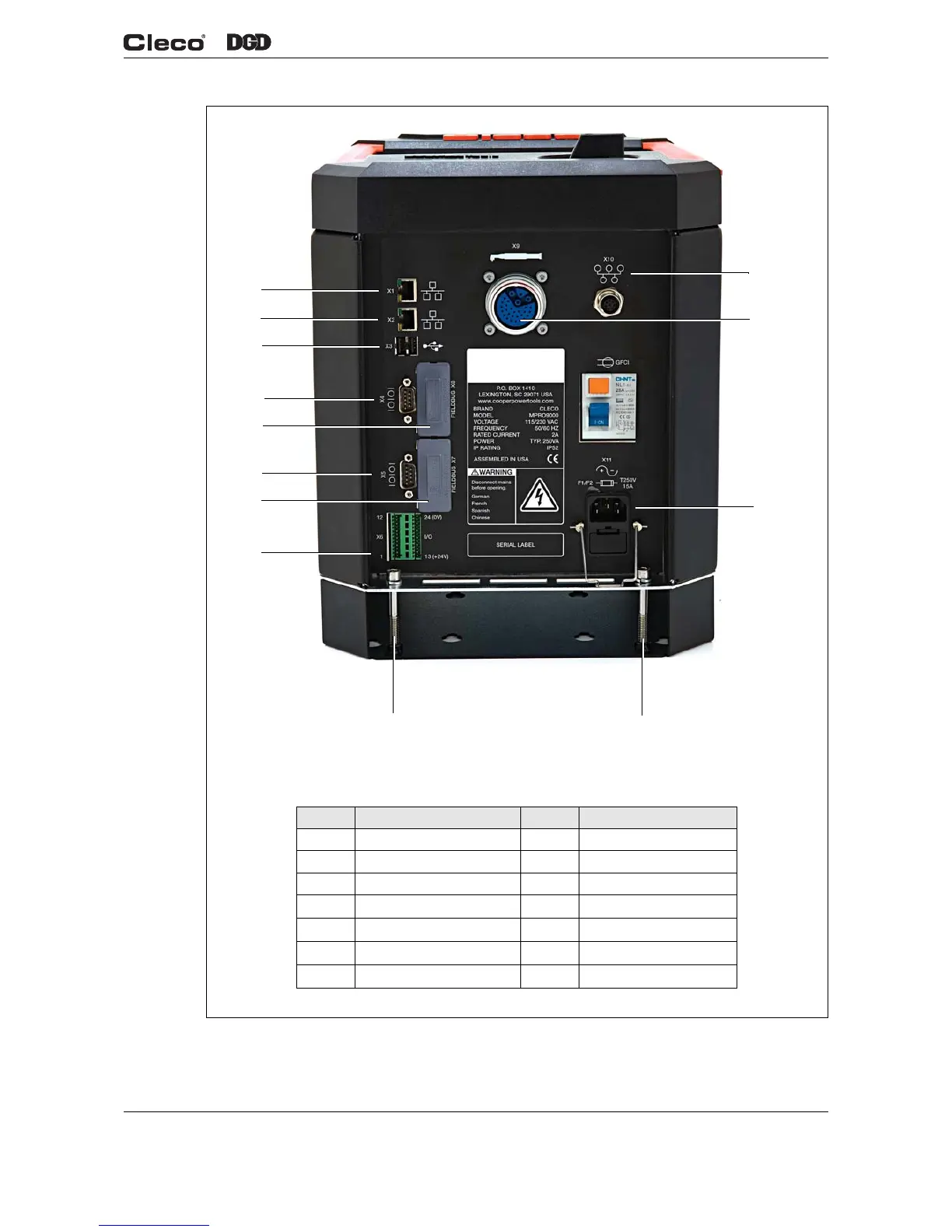
Fig. 2-2 Connector Locations
d01223_1.png
Position Description Position Description
1 System Bus Connector 8 Serial Connector #2
2 Tool Connector 9 Anybus Fieldbus
3 Power Connection 10 Serial Connector #1
4 Mounting Bracket Screw 11 USB ports (2)
5 Mounting Bracket Screw 12 Ethernet Connector #2
6 I/O Connectors 13 Ethernet Connector #1
7 Anybus Fieldbus
1
2
3
13
12
11
10
9
8
7
6
5
4

 Loading...