en03d441.fm, 07.04.2011 PL12EN-1001 2011-04 41
Programming
3
3.5 Run Screen
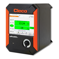
Fig. 3-12 Run Screen
From the Run Screen the user sees rundown data as it occurs. The Torque and Angle readings are dis-
played with a background color corresponding to the status of each.
The background is red if the value is too high, yellow if it is too low, and green if it is within limits. The current
tool model number, station name, and indicator labels are also displayed. The desired Application (1–99),
Tightening Group (1–32, if enabled), and Part ID (if enabled) are selectable using the keypad.
When enabled, the Part ID and Part ID Status boxes are displayed below the Tool and Application. When
allowed, the Part ID edit box may be used to manually enter a Part ID using the keypad or an attached key-
board.
Function
Indicates the status of Part ID Data Function (screen in the middle):
NOTE
When manually entering a Part ID, the <Enter> key must be pressed to validate the entry.
LED Data function Status
Red Not configured Part ID Data Function is configured to None.
Yellow None Part ID Configure Data is enabled, but the Part ID is
invalid or does not match any Configure Data entries.
Green Function XYZ Part ID Configure Data is enabled, and the current Part ID
has engaged function XYZ (see Communications Part ID
help screen for function definitions).
c01209en.png
 Loading...