en03d441.fm, 07.04.2011 PL12EN-1001 2011-04 51
Programming
3
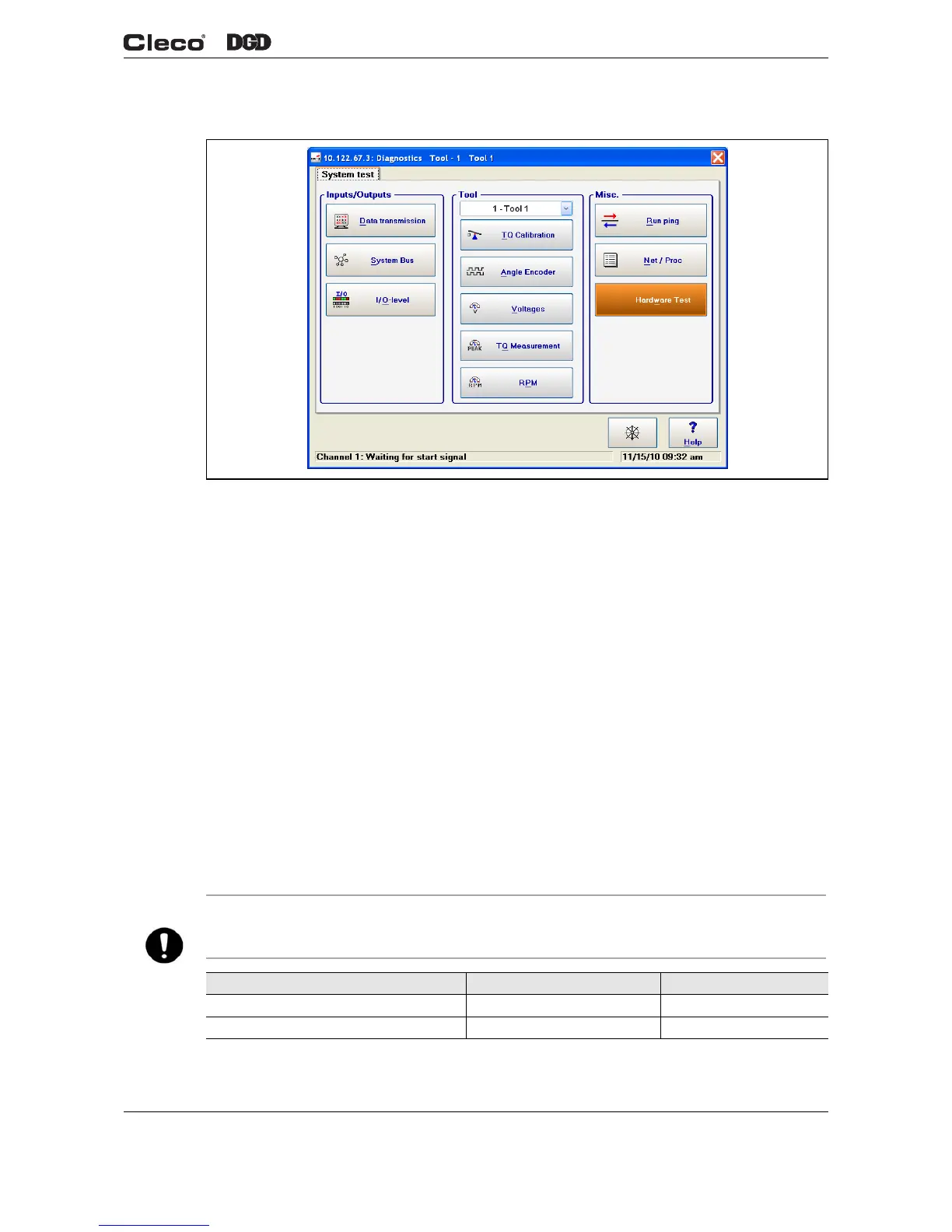
3.9 Diagnostics
Fig. 3-20 System Test
3.9.1 Inputs/Outputs
<Data Transmission>
Allows the user to analyse Serial and Ethernet data transmission.
<System Bus>
A Map of all available Arcnet users is displayed by node, status, ID, serial number, and software version.
<I/O-Level>
A light box for each available input and output is displayed to show the current status. Active input and out-
put signals are highlighted. You will find a detailed description of these signals under Advanced > Inputs,
Advanced > Outputs.
3.9.2 Tool
<TQ Calibration>
This test function cyclically recalibrates the system. The start switch must be released for this function! The
values "Offset Voltage" and "Full Scale Voltage" of the torque transducer are displayed. If a value is out of
tolerance, it is shown in red.
NOTE
Entering a password and viewing of a warning is required prior to running any "active" tool diagnostics.
Measurement Rated Value Tolerance
Offset Voltage 0 V ±200 mV
Full Scale Voltage 5 V ±150 mV
c01245en.png
 Loading...