52 PL12EN-1001 2011-04 en03d441.fm, 07.04.2011
Programming
3
<Angle Encoder>
The button <Start> starts the spindle with a speed of 30% of the maximum. After one revolution of the out-
put shaft (set angle 360 deg), measured with the tool resolver, it is stopped. During a permanently set dwell
time of 200ms any further angle pulses occurring are traced. The total result is shown as Actual Angle. The
Shutoff Torque displayed is the torque prevailing at shut-off or the maximum value reached during the dwell
time if that value is higher than the torque at shut-off.
If the test run is not terminated by a monitoring criterion, the total result equals or is higher than 360 degrees
and is evaluated as OK. Monitoring criteria are the torque of transducer 1 and a monitoring time. If the
torque of transducer 1 exceeds 15% of its calibration value (even during the dwell time), or if the monitoring
time of 5 seconds is elapsed, the test run is terminated with NOK.
The user must check, if the output shaft has actually turned by the value indicated (e.g. put mark on the
spindle). If the angle reached by the output shaft does not agree with the value displayed, either the angle
factor is or the resolver is defective.
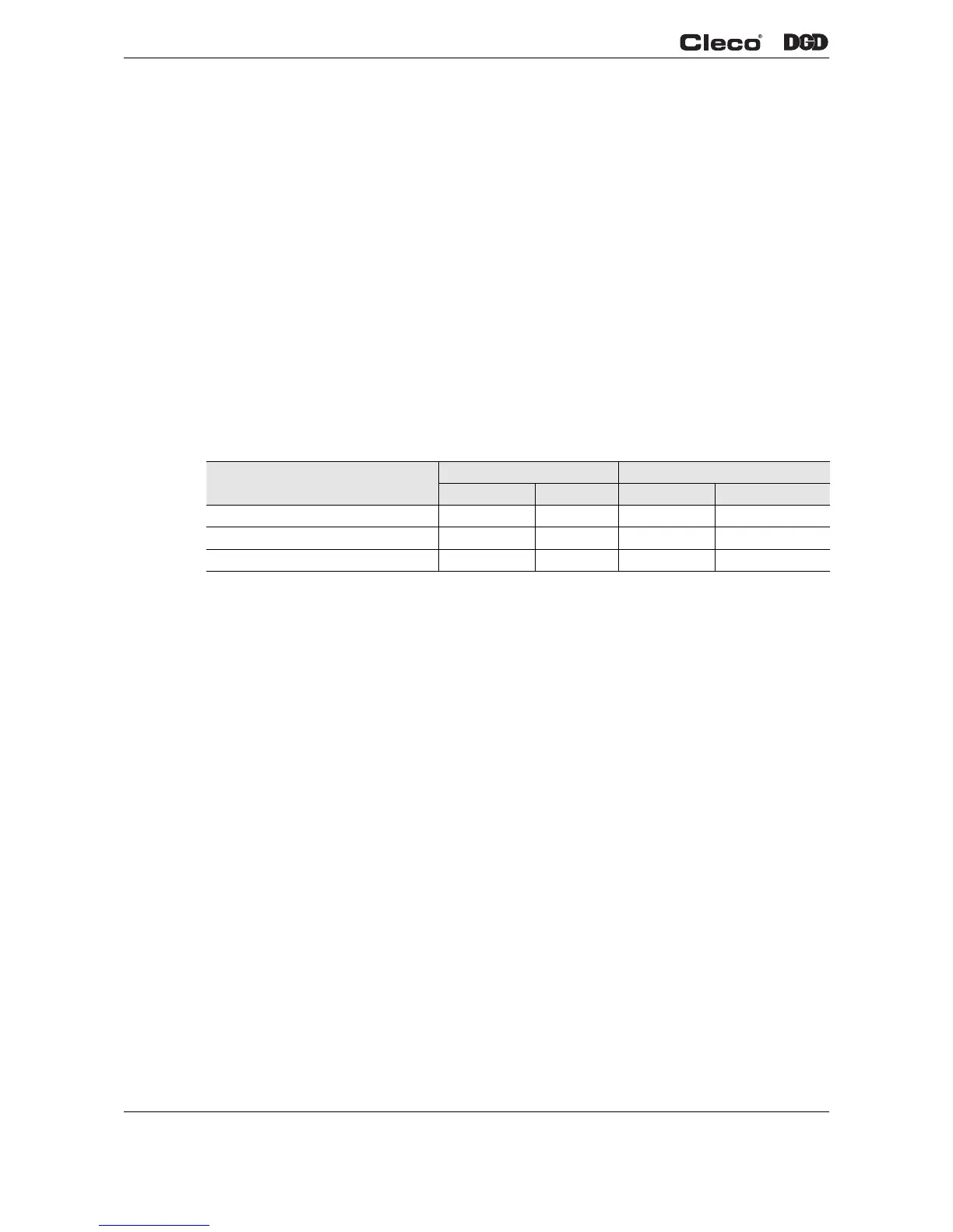
<Voltages>
The table displays the measured voltages of a channel.
These are the most important supply voltages on the voltages on the measuring board, required for proper
torque and angle measurement. Therefore, these must be monitored continuously. If a voltage is out of tol-
erance, it is shown in red.
<TQ Measurement>
This test function recalibrated the system with the values used immediately before the start of a rundown.
The spindle must therefore be free from load when this function is called! Then the tool is started at zero
speed and the torque is continuously measured and displayed. The field Current torque displays the current
torque, Peak torque displays the highest value measured since the start of the function. If Redundancy is
activated, the values of the second transducer are also displayed.
<RPM>
When you press <Start>, the spindle starts with maximum speed. The current output shaft speed is dis-
played. To achieve this, the angle factor must have been entered correctly, since the integrated speed mea-
surement is derived from the resolver signals. When you release the start switch the spindle stops. As a
safety function the torque is monitored by the tool transducer. If it exceeds 15% of its calibrated value, the
tachometer function is terminated.
Designation Voltage Corded tools Fixtured spindles
Rated Value Tolerance Rated Value Tolerance
Logic +5 V ±0.3 V +3.3 V +0.23 V/-0.06 V
Pos. analog +12 V ±0.6 V +12 V ±0.6 V
Neg. analog / Pos. Supply -12 V ±0.9 V +24 V ±3.6 V
 Loading...