Do you have a question about the Clevo P775DM2-G and is the answer not in the manual?
Provides a general overview of the information contained within the service manual for the notebook.
Details the technical specifications of the P775DM2 notebook, including processor, memory, and display options.
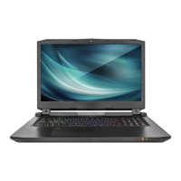
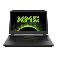
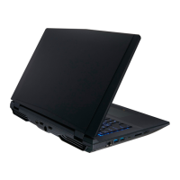
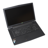
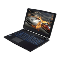
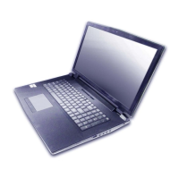
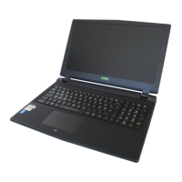
Identifies external parts of the notebook visible from the top view with the LCD panel open.
Highlights key parts and connectors on the top side of the mainboard.
Essential safety guidelines to prevent injury and component damage during maintenance tasks.
Lists the ordered steps for disassembling various parts of the notebook.
Step-by-step instructions for safely removing the notebook battery.
Procedure for removing and installing 2.5" SATA hard disk drives or SSDs.
Detailed instructions for safely removing and installing the CPU and heat sink unit.
Guide for removing and installing the video card, including heat sink procedures.
Table indicating the page numbers for specific part list illustrations.
Detailed list of motherboard components with part numbers.
Provides a high-level block diagram of the P775DM2 system architecture.
Detailed schematics for processor interfaces like DMI, FDI, PEG, and RSVD.
Circuit diagrams illustrating the DDR4 memory channels (CHA SO-DIMM).
Schematics detailing the M.2 PCIe 4x SSD connections.
Circuit diagrams for USB 3.1 ports and charging functionalities.
Illustrates various power rails and their distribution across the system.
Circuit diagrams for the embedded controller IT8587.
Schematics detailing the Thunderbolt interface connections and logic.
Visual representation of the power-on sequence and timing for system components.
Instructions on how to download the correct BIOS update files from the manufacturer's website.
Steps to prepare a bootable CD/DVD or USB Flash drive with BIOS files.
Procedure for using flash tools to update the system's BIOS.
| RAM | Up to 64GB DDR4 |
|---|---|
| Operating System | Windows 10 |
| Chipset | Intel HM170 |
| Bluetooth | Bluetooth 4.2 |
| Webcam | HD Webcam |
| Power Supply | 330W |
| Processor | Intel Core i7-7700K |
| Graphics | NVIDIA GeForce GTX 1070 / GTX 1080 |
| Display | 17.3" Full HD (1920 x 1080) |
| Storage | 2x M.2 SSD + 2x 2.5" HDD/SSD |
| Audio | 2x Speakers |
| LAN | Gigabit Ethernet |
| WLAN | 802.11ac |
| Keyboard | Backlit keyboard (RGB optional) |
| Ports | USB 3.0, USB Type-C, HDMI, Mini DisplayPort |
| Card Reader | SD/SDHC/SDXC |
| Battery | 8 Cell 82WH |