C l i m a t e M a s t e r Wa t e r-S o u r c e H e a t i n g a n d C o o l i n g S y s t e m s
C L I M A T E M A S T E R W A T E R - S O U R C E H E A T P U M P S
C o n s o l e s
R e v. : 0 8 / 1 3 / 1 0
8
CAUTION: Use only copper conductors for field
installed electrical wiring. Unit terminals are not
designed to accept other types of conductors.
All field installed wiring, including the electrical ground,
MUST comply with the National Electrical Code as
well as applicable local codes. In addition, all field low
voltage wiring must conform to the Class II temperature
limitations described in the NEC.
Consult the unit wiring diagram located on the inside of
the compressor access panel to ensure proper electrical
hookup. The installing (or electrical) contractor must
make the field connections shown in Figure 1 when
using field supplied disconnect.
Units have dual voltage (220-240V) control transformer.
The units are shipped for 240V operation. Modify the
transformer connection when the actual power supply
is 220 volts. Refer to the unit wiring diagram for details
of this procedure.
Make all final electrical connections with a length
of flexible conduit to minimize vibration and sound
transmission to the building.
Optional Wall-Mounted Thermostat
CCE WSHP units are built with standard internal
thermostats in either manual changeover (MCO)
or automatic changeover (ACO) configuration. No
external, field-installed low-voltage wiring is required.
When desired, the unit can be furnished with a 24-volt
control circuit which is field-wired to a ClimateMaster-
supplied accessory remote thermostat.
Zone integrity must be maintained to efficiently control
units or groups of units. Unless zones of control are
considered and accounted for, adjacent units may
operate in heating and cooling modes simultaneously.
Low-voltage wiring between the unit and the wall
thermostat must comply with all applicable electrical
codes (i.e., NEC and local codes), and be completed
before the unit is installed.
Table 2 lists recommended wire sizes and lengths
to install the thermostat. The total resistance of
low-voltage wiring must not exceed 1 ohm. Any
resistance in excess of 1 ohm may cause the control to
malfunction because of high voltage drop.
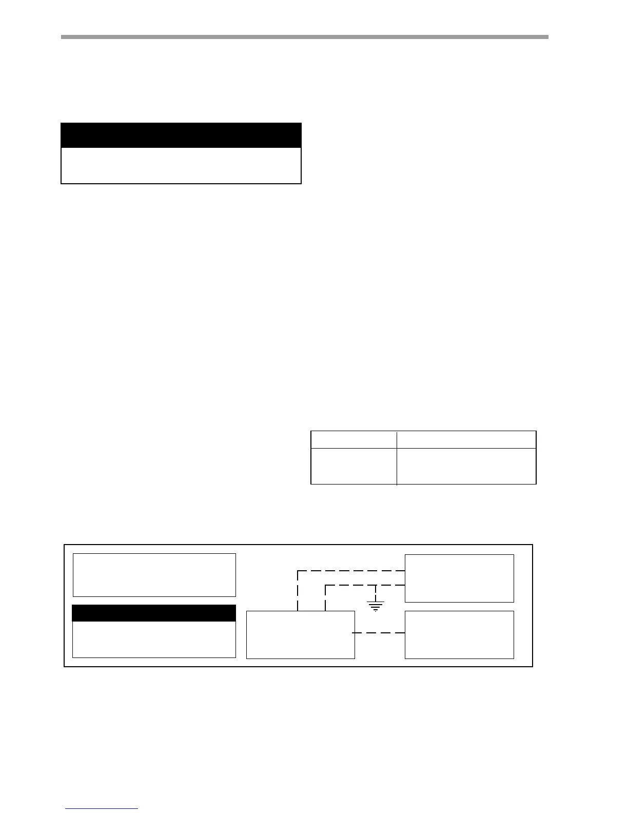
Field Supplied
Disconnect Switch
Heat Pump
A
Room Thermostat
B
A= Two power wires on single-phase units: three power wires on three-phase units. B= 1 heat /1 cool /
manual or Auto Change-over remote 24V thermostat. Note: All customer-supplied wiring to be copper
only and must conform to NEC and local electrical codes. Wiring shown with dashed lines must be field-
supplied and field-installed. "B" only required with systems employing remote mounted thermostats.
DISCONNECT ELECTRICAL POWER
SOURCE TO PREVENT INJURY OR DEATH
FROM ELECTRICAL SHOCK.
CAUTION: USE COPPER
CONDUCTORS ONLY TO PREVENT
EQUIPMENT DAMAGE.
Figure 1 Typical Field Installed Wiring
WIRE SIZE MAX. WIRE LENGTH*
18-Gauge 23 m
16-Gauge 38 m
14-Gauge 62 m
*Length = Physical distance from thermostat to unit.
Table 2 - Recommended Thermostat Wire Sizes
Electrical Wiring
To avoid possible injury or death due to electrical shock,
open the power supply disconnect switch and secure it in
an open position during installation.
� WARNING! �
� WARNING! �