THE SMART SOLUTION FOR ENERGY EFFICIENCY
35
climatemaster.com
Tranquility 16 (TC) Series
Rev.: 25 July, 2017
DXM Control - For detailed control information, see
CXM AOM (part # 97B0003N12), DXM AOM (part
#97B0003N13), Lon controller AOM (part #97B0013N01)
or MPC AOM (part # 97B0031N01).
-Slow Flash = 1 fl ash every 2 seconds
-Fast Flash = 2 fl ashes every 1 second
-Flash code 2 = 2 quick fl ashes, 10 second pause, 2
quick fl ashes, 10 second pause, etc.
-On pulse 1/3 second; off pulse 1/3 second
Field Selectable Inputs - Test mode: Test mode allows
the service technician to check the operation of the
control in a timely manner. By momentarily shorting
the test terminals, the DXM control enters a 20 minute
test mode period in which all time delays are sped
up 15 times. Upon entering test mode, the status
LED will fl ash a code representing the last fault. For
diagnostic ease at the thermostat, the alarm relay will
also cycle during test mode. The alarm relay will cycle
on and off similar to the status LED to indicate a code
representing the last fault, at the thermostat. Test
mode can be exited by shorting the test terminals for 3
seconds.
Retry mode: If the control is attempting a retry of a
fault, the status LED will slow fl ash (slow fl ash = one
fl ash every 2 seconds) to indicate the control is in
the process of retrying.
Field Confi guration Options - Note: In the following
fi eld confi guration options, jumper wires should
be clipped ONLY when power is removed from the
DXM control.
Water coil low temperature limit setting: Jumper
3 (JW3-FP1 Low Temp) provides fi eld selection of
temperature limit setting for FP1 of -1°C or -12°C
(refrigerant temperature).
DXM Controls
Not Clipped = -1°C. Clipped = -12°C.
Air coil low temperature limit setting: Jumper 2 (JW2-FP2
Low Temp) provides fi eld selection of temperature limit
setting for FP2 of -1°C or -12°C] (refrigerant temperature).
Note: This jumper should only be clipped
under extenuating circumstances, as
recommended by ClimateMaster technical
services.
Not Clipped = -1°C. Clipped = -12°C.
Alarm relay setting: Jumper 4 (JW4-AL2 Dry)
provides fi eld selection of the alarm relay
terminal AL2 to be jumpered to 24VAC or to
be a dry contact (no connection).
Not Clipped = AL2 connected to R.
Clipped = AL2 dry contact
(no connection).
Low pressure normally open: Jumper 1 (JW1-
LP norm open) provides fi eld selection for
low pressure input to be normally closed or
normally open.
Not Clipped = LP normally closed. Clipped =
LP normally open.
DIP Switches - Note: In the following fi eld
confi guration options, DIP switches should only be
changed when power is removed from the DXM
control.
DIP Package #1 (S1) - DIP Package #1 has 8 switches
and provides the following setup selections:
1.1 - Unit Performance Sentinel (UPS) disable: DIP Switch
1.1 provides fi eld selection to disable the UPS feature.
On = Enabled. Off = Disabled.
1.2 - Compressor relay staging operation: DIP 1.2
provides selection of compressor relay staging operation.
The compressor relay can be selected to turn on with
a stage 1 or stage 2 call from the thermostat. This
is used with dual stage units (2 compressors where
2 DXM controls are being used) or with master/
slave applications. In master/slave applications,
each compressor and fan will stage according to
its appropriate DIP 1.2 setting. If set to stage 2, the
compressor will have a 3 second on-delay before
energizing during a Stage 2 demand. Also, if set for stage
2, the alarm relay will NOT cycle during test mode.On =
Stage 1. Off = Stage 2.
1.3 - Thermostat type (heat pump or heat/cool): DIP 1.3
provides selection of thermostat type. Heat pump or
heat/cool thermostats can be selected. When in heat/
cool mode, Y1 is the input call for cooling stage 1; Y2 is
the input call for cooling stage 2; W1 is the input call for
heating stage 1; and O/W2 is the input call for heating
stage 2. In heat pump mode, Y1 is the input call for
compressor stage 1; Y2 is the input call for compressor
stage 2; W1 is the input call for heating stage 3 or
emergency heat; and O/W2 is the input call for reversing
valve (heating or cooling, depending upon DIP 1.4).
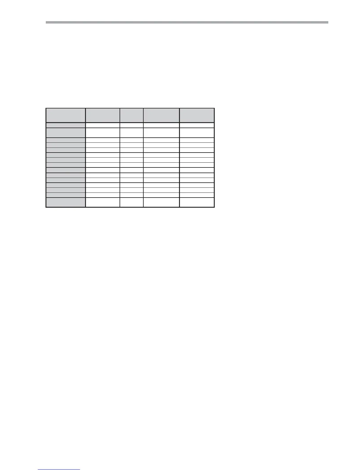
Table 6b: DXM LED And Alarm Relay Operations
 Loading...