THE SMART SOLUTION FOR ENERGY EFFICIENCY
7
climatemaster.com
Tranquility 16 (TC) Series
Rev.: 25 July, 2017
Horizontal Installation
Horizontal Unit Location
Units are not designed for outdoor installation. Locate
the unit in an INDOOR area that allows enough space
for service personnel to perform typical maintenance
or repairs without removing unit from the ceiling.
Horizontal units are typically installed above a false
ceiling or in a ceiling plenum. Never install units in
areas subject to freezing or where humidity levels could
cause cabinet condensation (such as unconditioned
spaces subject to 100% outside air). Consideration
should be given to access for easy removal of the fi lter
and access panels. Provide suffi cient room to make
water, electrical, and duct connection(s).
If the unit is located in a confi ned space, such as a
closet, provisions must be made for return air to freely
enter the space by means of a louvered door, etc. Any
access panel screws that would be diffi cult to remove
after the unit is installed should be removed prior to
setting the unit. Refer to Figure 3 for an illustration of
a typical installation. Refer to unit submittal data or
engineering design guide for dimensional data.
In limited side access installations, pre-removal of the
control box side mounting screws will allow control box
removal for future servicing.
Conform to the following guidelines when selecting
unit location:
1. Provide a hinged access door in concealed-spline
or plaster ceilings. Provide removable ceiling
tiles in T-bar or lay-in ceilings. Refer to horizontal
unit dimensions for specifi c series and model
in unit submittal data. Size the access opening
to accommodate the service technician during
the removal or replacement of the compressor,
control, or blower assembly. Provide access to
hanger brackets, water valves and fi ttings. Provide
screwdriver clearance to access panels, discharge
collars and all electrical connections.
2. DO NOT obstruct the space beneath the unit
with piping, electrical cables and other items that
prohibit future removal of components or the unit
itself.
3. Use a manual portable jack/lift to lift and support
the weight of the unit during installation and
servicing.
The installation of water source heat pump units and all
associated components, parts and accessories which
make up the installation shall be in accordance with
the regulations of ALL authorities having jurisdiction
and MUST conform to all applicable codes. It is the
responsibility of the installing contractor to determine
and comply with ALL applicable codes and regulations.
Mounting Horizontal Units
Horizontal units have 4 hanger brackets partially
attached at the factory, one at each corner. Enclosed
within the unit there is a hanger kit hardware bag
containing vibration isolation grommets, washers,
screws and a hanger installation instruction page. One
additional screw from the hardware bag must be added
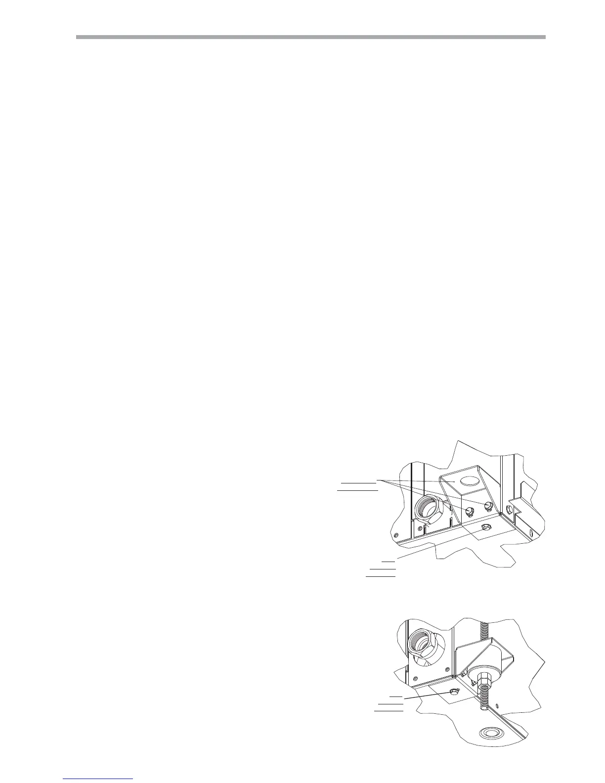
to each hanger bracket before unit installation.Tighten
each screw to 75 in-lbs (8.5 Nm). See Figure 1. Refer
to the hanger installation instruction page contained
in the hardware bag for details of fi nal hanger bracket
attachment and unit suspension. See Figure 1a.
Use four (4) fi eld supplied threaded rods and factory
provided vibration isolators to suspend the unit. Safely
lift the unit into position supporting the bottom of the
unit. Ensure the top of the unit is not in contact with
any external objects. Connect the top end of the 4
all-thread rods, slide rods through the brackets and
grommet then assemble washers and double nuts at
each rod. Ensure that the unit is approximately level
and that the threaded rod extends past the nuts.
Pitch the unit toward the drain as shown in Figure 2
to improve the condensate drainage. On small units
(less than 8.8 kW) ensure that unit pitch does not cause
condensate leaks inside the cabinet.
VIEW CONDENSATE END
BEFORE GROMMET AND HARDWARE
(Unit pictured for hanger bracket reference).
(Drain hardware may vary per unit model)
INSTALLED
AT FACTORY
ADD
BEFORE
HANGING
VIEW WATER CONNECTION END
FULLY ASSEMBLED
(Unit pictured for hanger bracket reference)
(Water hardware may vary per unit model)
ADD
BEFORE
HANGING
Figure 1a:
Figure 1: Hanger Bracket
 Loading...