15
climatemaster.com
THE SMART SOLUTION FOR ENERGY EFFICIENCY
Packaged Units
Rev.: 1/06/09B
Horizontal Installation
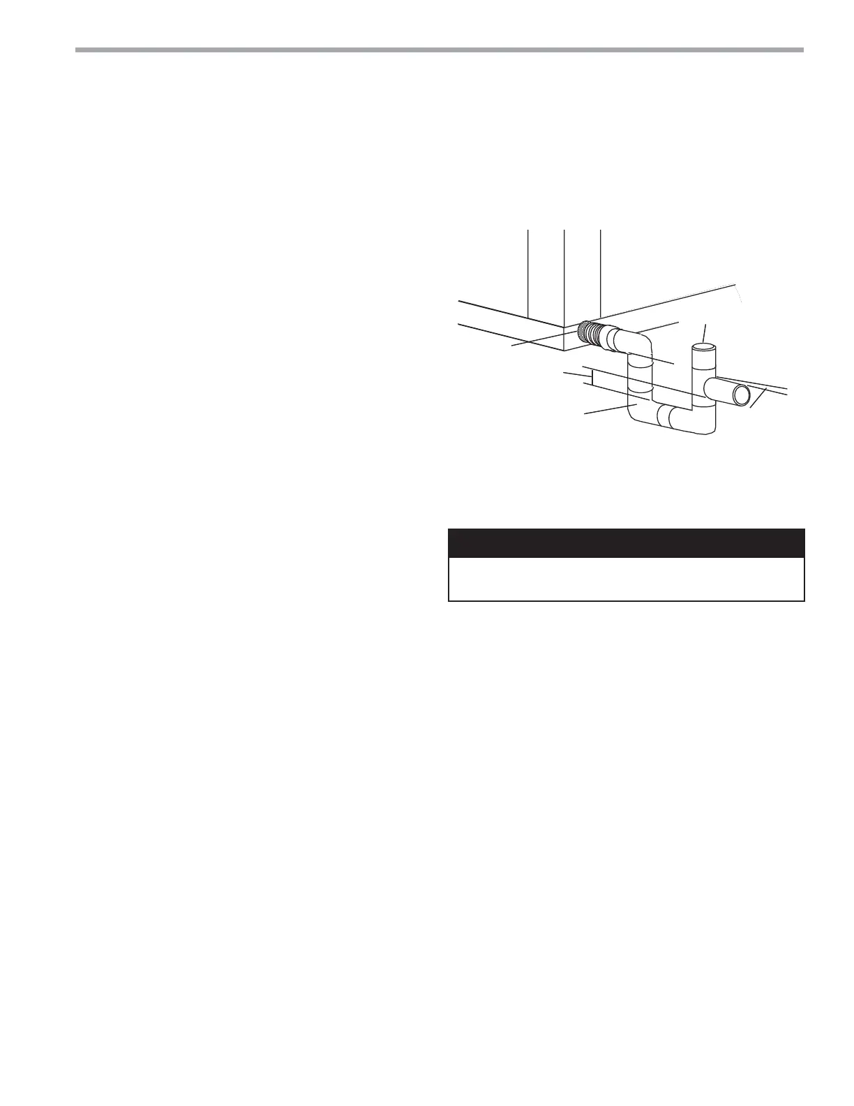
*3/4" IPT
Trap Depth
1.5" [38mm]
Min 1.5"
[38mm]
1/4" per foot
(21mm per m)
drain slope
3/4" PVC or
Copper by others
Rev.: 10/26/06D
Vent (below top of
drain line)
* Some units include a painted drain
connection. Using a threaded pipe or
similar device to clear any excess paint
accumulated inside this fitting may
ease final drain line installation.
Figure 6: Horizontal Condensate Connection
CAUTION! Ensure condensate line is pitched toward drain
1/4” per foot [21mm per m] of run.
Condensate Piping – Horizontal Units
CAUTION!
Pitch the unit toward the drain as shown in Figure 2 to
improve the condensate drainage. On small units (less
than 2.5 tons/8.8 kW), insure that unit pitch does not
cause condensate leaks inside the cabinet.
Install condensate trap at each unit with the top of
the trap positioned below the unit condensate drain
connection as shown in Figure 6. Design the depth of
the trap (water-seal) based upon the amount of ESP
capability of the blower (where 2 inches [51mm] of
ESP capability requires 2 inches [51mm] of trap depth).
As a general rule, 1-1/2 inch [38mm] trap depth is the
minimum.
Each unit must be installed with its own individual trap
and connection to the condensate line (main) or riser.
Provide a means to fl ush or blow out the condensate
line. DO NOT install units with a common trap and/or vent.
Always vent the condensate line when dirt or air
can collect in the line or a long horizontal drain line
is required. Also vent when large units are working
against higher external static pressure than other units
connected to the same condensate main since this may
cause poor drainage for all units on the line. WHEN A
VENT IS INSTALLED IN THE DRAIN LINE, IT MUST BE
LOCATED AFTER THE TRAP IN THE DIRECTION OF
THE CONDENSATE FLOW.
 Loading...