45
climatemaster.com
THE SMART SOLUTION FOR ENERGY EFFICIENCY
Packaged Units
Rev.: 1/06/09B
Electrical - Power & Low Voltage Wiring
Special Note for ARI Testing: To achieve rated
airfl ow for ARI testing purposes on all PSC products,
it is necessary to change the fan speed to “HI” speed.
When the heat pump has experienced less than 100
operational hours and the coil has not had suffi cient time
to be “seasoned”, it is necessary to clean the coil with a
mild surfactant such as Calgon to remove the oils left by
manufacturing processes and enable the condensate to
properly “sheet” off of the coil.
ELECTRICAL - LOW VOLTAGE WIRING
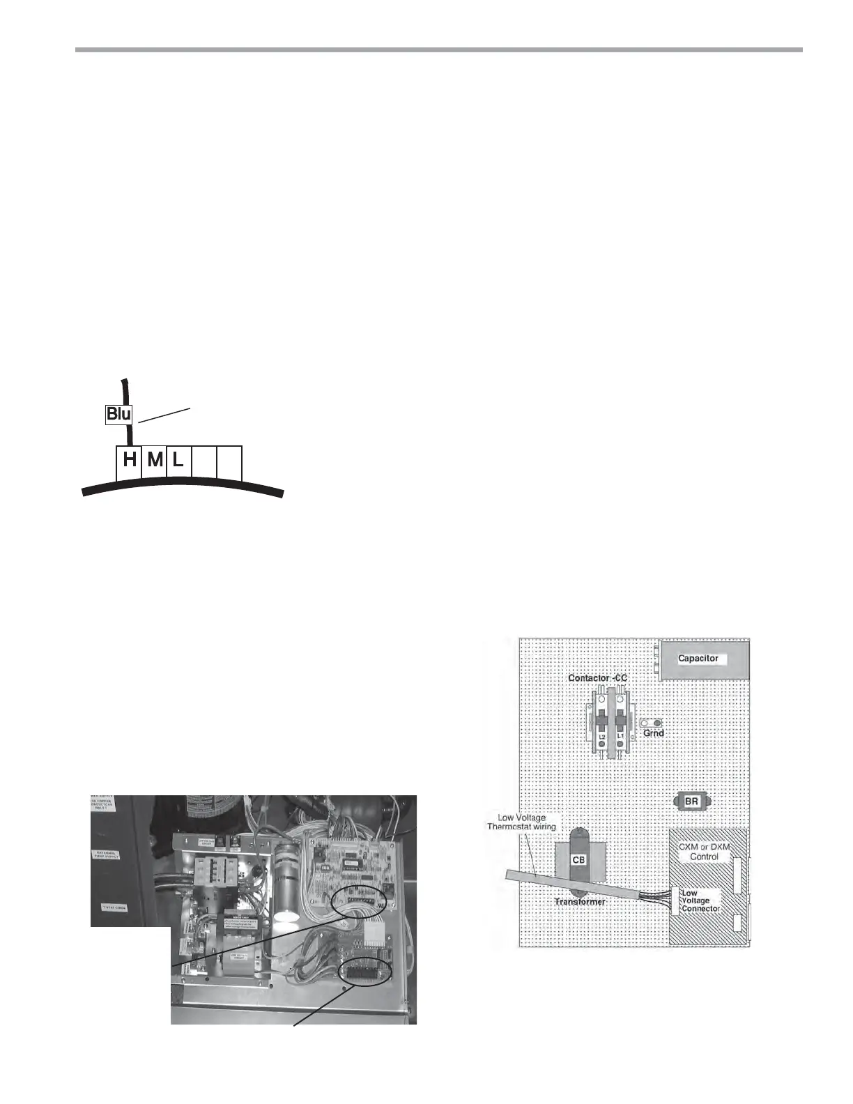
Connect the blue wire to:
H for High speed fan
M for Medium speed fan
L for Low speed fan
Medium is factory setting
Fan Motor
Figure 17: PSC Motor Speed Selection
Thermostat Connections
The thermostat should be wired directly to the CXM or
DXM board (units with PSC fan). Units with optional
ECM motor include factory wiring from the CXM or DXM
board to the ECM interface board. Thermostat wiring for
these units should be connected to the ECM interface
board. Figure 18 shows wiring for GS/GR/GC units;
fi gure 19 should be used for TT/TS units with PSC or
optional ECM motor. See “Electrical – Thermostat” for
specifi c terminal connections. Review the appropriate
AOM (Application, Operation and Maintenance) manual
for units with DDC controls.
Figure 18: TT/TS Low Voltage Field Wiring
Low voltage fi eld wiring for units with ECM fan
Low voltage
fi eld wiring
for units with
PSC FAN
(ECM board
will not be
present)
Figure 19: GS/GR/GC Low Voltage Field Wiring
Low Water Temperature Cutout Selection
The CXM/DXM control allows the fi eld selection of low
water (or water-antifreeze solution) temperature limit
by clipping jumper JW3, which changes the sensing
temperature associated with thermistor FP1. Note that
the FP1 thermistor is located on the refrigerant line
between the coaxial heat exchanger and expansion
device (TXV or cap tube). Therefore, FP1 is sensing
refrigerant temperature, not water temperature, which is
a better indication of how water fl ow rate/temperature is
affecting the refrigeration circuit.
The factory setting for FP1 is for systems using water
(30°F [-1.1°C] refrigerant temperature). In low water
temperature (extended range) applications with
antifreeze (most ground loops), jumper JW3 should be
clipped as shown in Figure 20 to change the setting
to 10°F [-12.2°C] refrigerant temperature, a more
suitable temperature when using an antifreeze solution.
All ClimateMaster units operating with entering water
temperatures below 59°F [15°C] must include the
optional water/refrigerant circuit insulation package to
prevent internal condensation. GC series equipment is
not rated for extended range applications.
 Loading...