44
ClimateMaster Water-Source Heating and Cooling Systems
CLIMATEMASTER WATER-SOURCE HEAT PUMPS
Packaged Units
Rev.: 1/06/09B
Electrical - Power Wiring
CAUTION!
Use only copper conductors for fi eld installed
electrical wiring. Unit terminals are not designed to accept other
types of conductors.
Electrical - Line Voltage
All fi eld installed wiring, including electrical ground,
must comply with the National Electrical Code as well
as all applicable local codes. Refer to the unit electrical
data for fuse sizes. Consult wiring diagram for fi eld
connections that must be made by the installing (or
electrical) contractor. All fi nal electrical connections must
be made with a length of fl exible conduit to minimize
vibration and sound transmission to the building.
General Line Voltage Wiring
Be sure the available power is the same voltage and
phase shown on the unit serial plate. Line and low
voltage wiring must be done in accordance with local
codes or the National Electric Code, whichever is
applicable.
Figure 15: TT/TS Single Phase Line Voltage Field
Wiring. Three phase wiring is similar except that
all three power wires are directly connected to the
contactor.
Unit Power Supply
(see electrical table for
wire and breaker size)
Note: 460V units with
ECM motor require
a neutral wire.
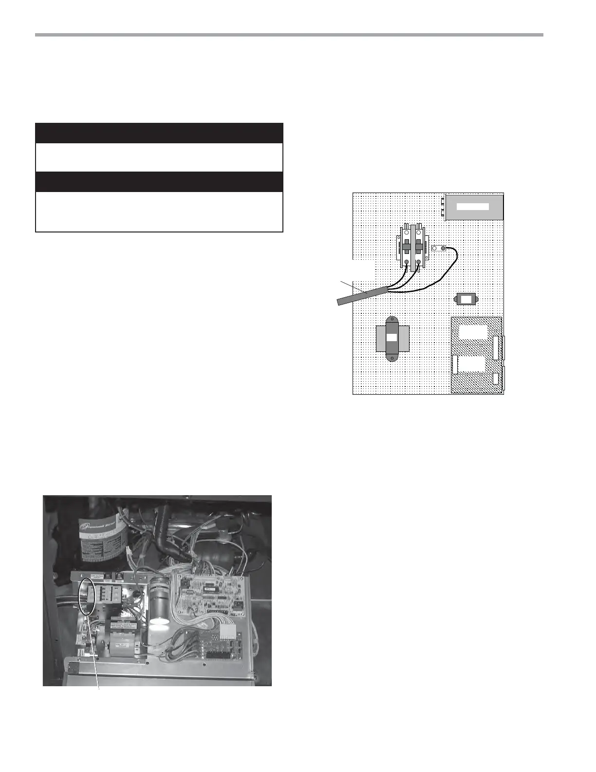
Figure 16: GS/GR/GC Single Phase Line Voltage Field
Wiring. Three phase wiring is similar except that
all three power wires are directly connected to the
contactor.
Transformer
CXM
Control
Contactor -CC
BR
Low
Voltage
Connector
CB
L2
L1
Unit Power Supply
See electrical table for
breaker size
Grnd
Rev.: 5/17/01 B
Capacitor
Blower Speed Selection – Units with PSC Motor
PSC (Permanent Split Capacitor) blower fan speed can
be changed by moving the blue wire on the fan motor
terminal block to the desired speed as shown in Figure
17. Optional ECM motor (TT/TS units only) speeds are
set via low voltage controls (see “ECM Blower Control”).
Most ClimateMaster units are shipped on the medium
speed tap. Consult submittal data or engineering design
guide for specifi c unit airfl ow tables. Typical unit design
delivers rated airfl ow at nominal static (0.15 in. w.g.
[37Pa]) on medium speed and rated airfl ow at a higher
static (0.4 to 0.5 in. w.g. [100 to 125 Pa]) on high speed
for applications where higher static is required. Low
speed will deliver approximately 85% of rated airfl ow at
0.10 in. w.g. [25 Pa]. An optional high static blower is
available on some models.
WARNING! Disconnect electrical power source to prevent
injury or death from electrical shock.
CAUTION!
WARNING!
Power Connection
Line voltage connection is made by connecting the
incoming line voltage wires to the “L” side of the
contractor as shown in Figures 15 and 16. Consult
Tables 4a and 4g for correct fuse size.
Transformer
All commercial dual voltage units are factory wired for
208/60/1 or 240/50/1. If supply voltage is 230/60/1 or
220/50/1, installer must rewire transformer. See wire
diagram for connections.
 Loading...