Troubleshooting Guide -
Tranquility
®
Digital (DXM2) Packaged Units
Rev.: 01/15/14
40
Geothermal Heat Pump Systems
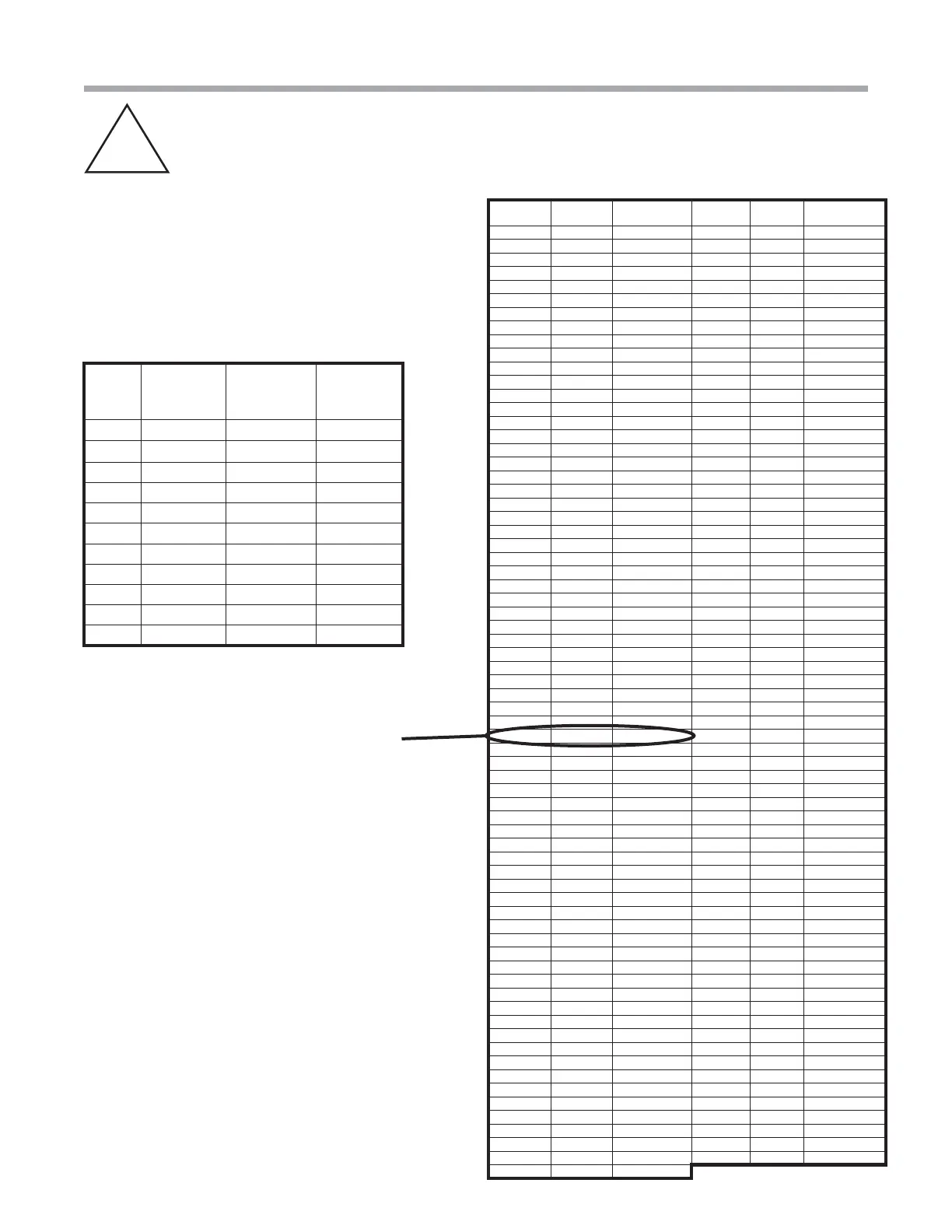
Nominal resistance at various temperatures Table
Verifying a Thermistor
B-B
1% Sensor Calibration Points Table
Thermistor Temperature Sensors – The thermistors used
with the DXM2 are NTC (negative temperature coeffi cient)
type. Table 7 shows the replacement part numbers for
the LT1 and LT2 thermistors. The sensors have a 1%
tolerance and follow the characteristics shown in ‘1%
Sensor Calibration Points Table’. The ‘Nominal resistance at
various temperatures Table’ shows the nominal resistance
at any given temperature and can be used for fi eld service
reference. The sensor will use a minimum of 24 awg wire.
Temp (ºC) Temp (ºF)
Resistance
(kOhm)
Temp (ºC) Temp (ºF)
Resistance
(kOhm)
-17.8 0.0 85.34 55 131.0 2.99
-17.5 0.5 84.00 56 132.8 2.88
-16.9 1.5 81.38 57 134.6 2.77
-12 10.4 61.70 58 136.4 2.67
-11 12.2 58.40 59 138.2 2.58
-10 14.0 55.30 60 140.0 2.49
-9 15.8 52.38 61 141.8 2.40
-8 17.6 49.64 62 143.6 2.32
-7 19.4 47.05 63 145.4 2.23
-6 21.2 44.61 64 147.2 2.16
-5 23.0 42.32 65 149.0 2.08
-4 24.8 40.15 66 150.8 2.01
-3 26.6 38.11 67 152.6 1.94
-2 28.4 36.18 68 154.4 1.88
-1 30.2 34.37 69 156.2 1.81
0 32.0 32.65 70 158.0 1.75
1 33.8 31.03 71 159.8 1.69
2 35.6 29.50 72 161.6 1.64
3 37.4 28.05 73 163.4 1.58
4 39.2 26.69 74 165.2 1.53
5 41.0 25.39 75 167.0 1.48
6 42.8 24.17 76 168.8 1.43
7 44.6 23.02 77 170.6 1.39
8 46.4 21.92 78 172.4 1.34
9 48.2 20.88 79 174.2 1.30
10 50.0 19.90 80 176.0 1.26
11 51.8 18.97 81 177.8 1.22
12 53.6 18.09 82 179.6 1.18
13 55.4 17.26 83 181.4 1.14
14 57.2 16.46 84 183.2 1.10
15 59.0 15.71 85 185.0 1.07
16 60.8 15.00 86 186.8 1.04
17 62.6 14.32 87 188.6 1.01
18 64.4 13.68 88 190.4 0.97
19 66.2 13.07 89 192.2 0.94
20 68.0 12.49 90 194.0 0.92
21 69.8 11.94 91 195.8 0.89
22 71.6 11.42 92 197.6 0.86
23 73.4 10.92 93 199.4 0.84
24 75.2 10.45 94 201.2 0.81
25 77.0 10.00 95 203.0 0.79
26 78.8 9.57 96 204.8 0.76
27 80.6 9.16 97 206.6 0.74
28 82.4 8.78 98 208.4 0.72
29 84.2 8.41 99 210.2 0.70
30 86.0 8.06 100 212.0 0.68
31 87.8 7.72 101 213.8 0.66
32 89.6 7.40 102 215.6 0.64
33 91.4 7.10 103 217.4 0.62
34 93.2 6.81 104 219.2 0.60
35 95.0 6.53 105 221.0 0.59
36 96.8 6.27 106 222.8 0.57
37 98.6 6.01 107 224.6 0.55
38 100.4 5.77 108 226.4 0.54
39 102.2 5.54 109 228.2 0.52
40 104.0 5.33 110 230.0 0.51
41 105.8 5.12 111 231.8 0.50
42 107.6 4.92 112 233.6 0.48
43 109.4 4.72 113 235.4 0.47
44 111.2 4.54 114 237.2 0.46
45 113.0 4.37 115 239.0 0.44
46 114.8 4.20 116 240.8 0.43
47 116.6 4.04 117 242.6 0.42
48 118.4 3.89 118 244.4 0.41
49 120.2 3.74 119 246.2 0.40
50 122.0 3.60 120 248.0 0.39
51 123.8 3.47 121 249.8 0.38
52 125.6 3.34 122 251.6 0.37
53 127.4 3.22 123 253.4 0.36
54 129.2 3.10
Example: See images 4 and 5 on previous page.
If your temperature reading is 71.2 with 11.07 ohms, your
sensor is good.
All thermistors in Tranquility
®
units can use this chart for
verifi cation
Temp
(°F)
Minimum
Resistance
(Ohm)
Maximum
Resistance
(Ohm)
Nominal
Resistance
(Ohm)
78.5 9523 9715 9619
77.5 9650 9843 9746
76.5 10035 10236 10135
75.5 10282 10489 10385
33.5 30975 31598 31285
32.5 31871 32512 32190
31.5 32653 33310 32980
30.5 33728 34406 34065
1.5 80624 82244 81430
0.5 83327 85002 84160
0.0 84564 86264 85410