57
Troubleshooting Guide -
Tranquility
®
Digital (DXM2) Packaged Units
Rev.: 01/15/14
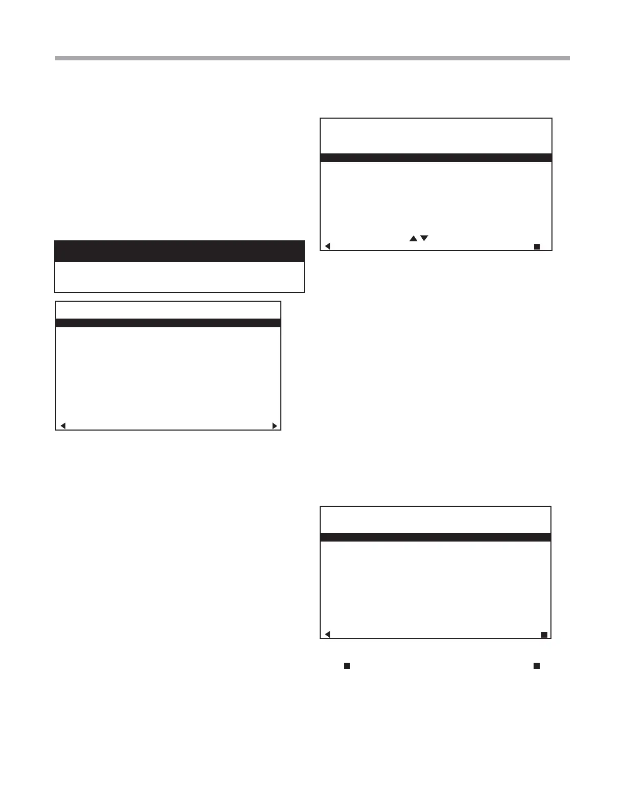
UNIT CONFIGURATION
CURRENT CONFIG TE026
HEAT PUMP FAMILY TE
HEAT PUMP SIZE 026
BLOWER TYPE ECM
LOOP CONFIG VS PUMP
PARALLEL
SELECT OPTION
PREVIOUS SAVE
VARIABLE SPD INTERNAL
PUMP CONFIGURATION
PUMP CONTROL DELTA T
HEATING DELTA T 7
COOLING DELTA T 10
MAXIMUM HEAT LWT 80
MINIMUM COOL LWT 40
PREVIOUS SELECT
• Compressor ASCD (Anti-Short Cycle Delay
(default stored in control) – valid range: 5 to 8
(in 1 minute increments)
NOTE 1: The Compressor Anti-Short Cycle Delay setting
provides equipment protection by forcing the compressor to
wait a few minutes before restarting.
NOTE 2: If multiple units are connected to one thermostat,
refer to section 3.6 for unit selection.
3.4 PUMP CONFIGURATION
vFlow™ vs internal flow control pump can be controlled either
through temperature differential (Delta T) or can be set to
specific speed (fixed; % of full speed for each heat and cool
stage).
Configure temperature differentials at the thermostat for
vFlow™ units with an internal flow control pump.
Adjust the Pump Configuration settings using the up/down
arrow buttons. Press the center button to select each item.
• Heating Delta T (default stored in control) –
valid range: 4 to 12ºF (in 1ºF increments)
• Cooling Delta T (default stored in control) –
valid range: 9 to 20ºF (in 1ºF increments)
Maximum Heat LWT (valid range based on specifi c model;
refer to model IOM). Minimum Cool LWT (valid range based
on specifi c model; refer to model IOM).
NOTE: Refer to section 3.6.3 for multi-unit confi guration
instructions.
To control vs pump by fi xed speed, select ‘Pump Control’,
press
, use down arrow to select ‘Fixed’, and press to
save.
Default stored in control. Valid range: 15% - 90% (in 1%
increments)
Heating Stage 1 Cooling Stage 1
Heating Stage 2 Cooling Stage 2
If Pump Confi guration is set to ‘VS PUMP PARALLEL’, valid
range changes to 50-90% (in 1% increments).
OPTION SELECTION
MOTORIZED VALVE OFF
COMPRESSOR ASCD 5
PREVIOUS NEXT
3.3 UNIT CONFIGURATION
Adjust the Unit Confi guration settings including Heat
Pump Family, Heat Pump Size, Blower Type, and Loop
Confi guration using the up/down arrow buttons. Press the
center button to select each item.
• Heat Pump Family (default stored in control) –
valid range: TE, TY, TES, TEP, TRT, TSM
• Heat Pump Size (default stored in control) – valid
range: depends on Heat Pump Family setting
• Blower Type (default stored in control) – valid
range: NONE, PSC–2SPD, ECM, PSC–1SPD
• Loop Confi g (default stored in control) – valid
range: Other, VS PUMP SINGLE, VS PUMP
PARALLEL, MOD VALVE, MOD VALVE MIN POS
Airfl ow, pump and valves can be confi gured from ‘System
Confi guration’ screen.
Select ‘VS PUMP PARALLEL’ when applying an internal
variable speed fl ow controller with other fl ow controllers on a
single loop in parallel.
NOTE: Refer to section 3.6.3 for multi-unit confi guration
instructions.
CAUTION!
CAUTION! This is a Commercial option only and does not
alter Residential unit operation.
ATC32U01 Thermostat Screens and Set Up