16
English
TERMINAL EVOLUTION
ELECTRICAL CONNECTIONS
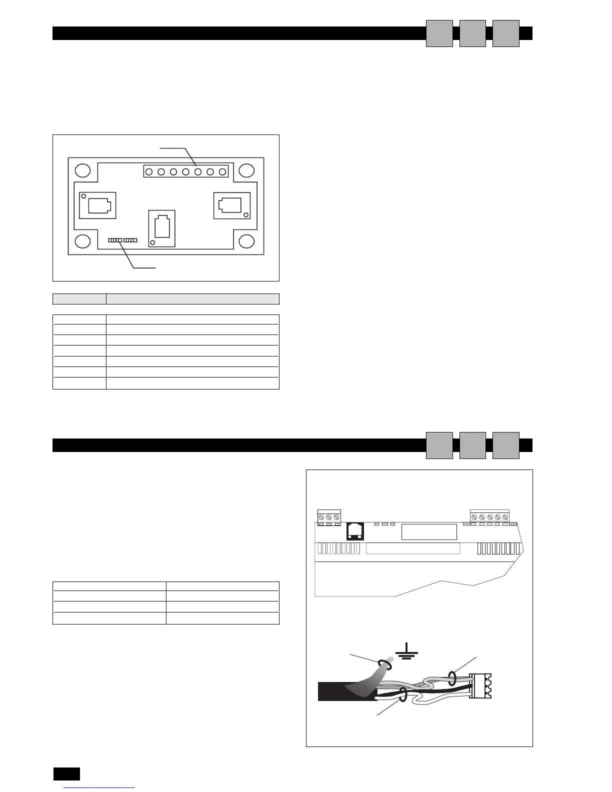
AIU
CONNECTION BETWEEN PC01 BOARDS
AIU
The electrical connections must be completed when the units are
off and disconnected from the power supply.
The network can have different configurations, according to the
maximum distance of the connections between the boards and
the remote terminal; for the connections between the remote
terminal and the main board, a 'T' shunt may be required, as
shown in the drawing.
If both the jumpers are installed between 2 and 3 the flow of cur-
rent is interrupted between the connectors separated by the
dashed line.
If power is required on all the connectors, both the jumpers must
be installed between 1 and 2.
Terminal 0 is an auxiliary terminal and can be used to earth the
shield of the cable; the 'T' shunt must in any case be connected to
a metallic part of the unit that is already earthed.
MAXIMUM DISTANCE BETWEEN THE TERMINAL
AND THE BOARD
1 For local terminals the connection to the main board is already
made using a 3-pair cable and 6-pin telephone connector. The
length of this cable generally does not exceed 3 metres.
2 The remote terminals can be connected to the main board
using the type of telephone cable described in point 1, with a
maximum distance of 50 metres.
3 For greater distances, up to a maximum of 200 metres, a shield-
ed cable must be used (six lead cable with shield and twisted
pairs, AWG24, resistance < 80 ohm/M). The cable may have 3
or 2 pairs, depending on whether the power needs to be sup-
plied to the terminals. The cable is not supplied by CLI-
MAVENETA HOME SYSTEM s.r.l.
AWG 24 cables with two twisted pairs plus shield, such as the
Belden 8723 or 8102, and AWG 24 cables with three twisted
pairs plus shield, Belden 8103 or similar, are recommended.
terminal function
0 Earth (shield)
1 +VRL ≈ 30Vcc
2 Gnd
3 Rx/Tx-
4 Rx/Tx+
5 Gnd
6 +VRL ≈ 30Vcc
In this configuration, the local terminal is already connected to
the main board using a telephone cable.
To complete the network wiring, the control boards should be
connected in parallel using a shielded cable and with terminal J11
as the reference, as shown in the figure.
IMPORTANT: the polarity of the network must be observed:
The RX/TX+ on one board must be connected to the RX/TX+
on the other boards; the same is true for RX/TX-.