18
English
TERMINAL EVOLUTION
CONNECTION TO THE REMOTE TERMINAL FROM THE BOARD
AIU
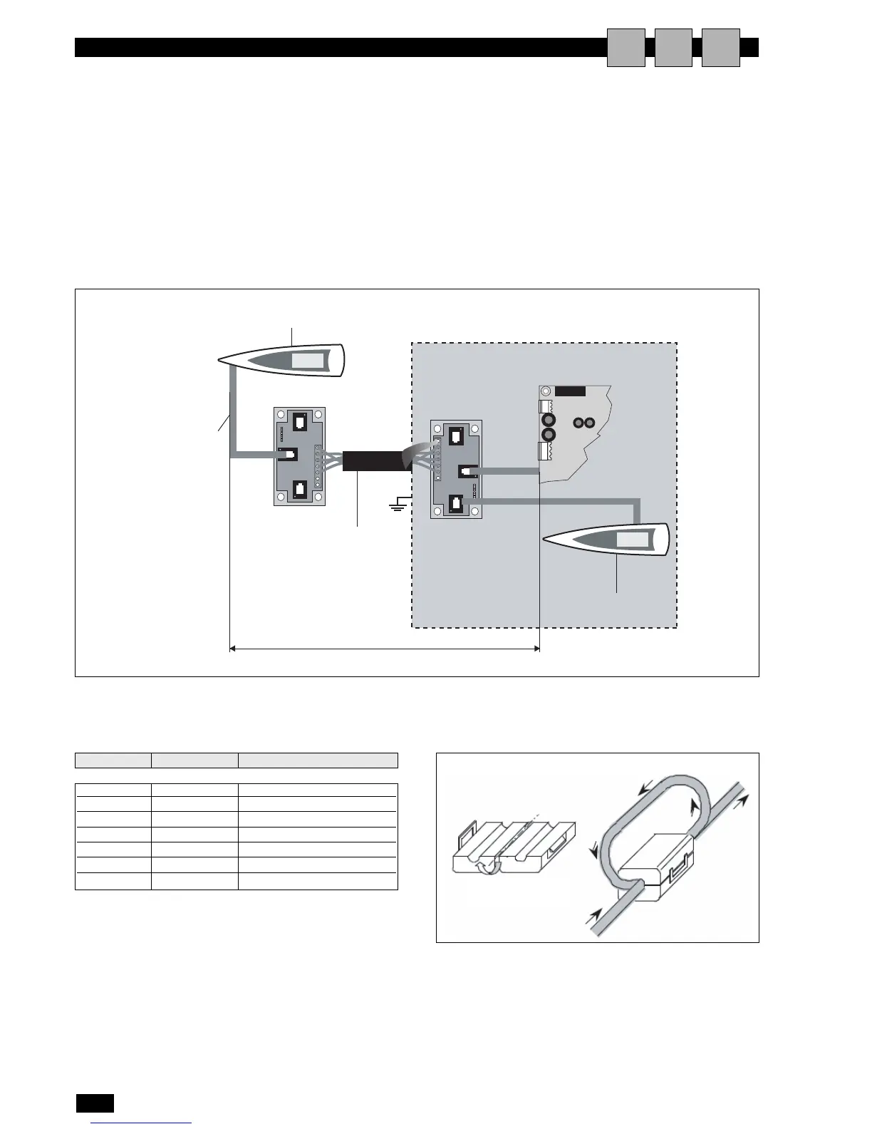
EXAMPLE OF CONNECTION TO THE REMOTE TER-
MINAL POWERED BY THE BOARD
This configuration requires:
1 the use of two 'T' shunts: one fitted on the unit and one near
the remote terminal;
2 the use of the 3x2 shielded cable, so that the power to the
remote terminal is also supplied by the board on unit 1, con-
nected using the 'T' shunt;
3 near the terminal, insert the ferrite to reduce any electromag-
netic disturbance.
Remote termi-
nal no. 32
Term. no. 11
Board no. 1
Three-pair cable
pairs with 6-pin
telephone con-
nector.
Three-pair shielded cable: 3 x 2 x
AWG 24 (six lead cable with
shield and twisted pairs,AWG24,
resistance < 80ohm/M). Remote
terminal no. 32 Board no. 1 Term.
Maximum distance between terminal/board: 200 m
FERRITE
terminal function cable connections
0 Earth shield
1 + VRL ≈ 30Vcc
2 Gnd First pair
3 Rx/Tx - Second pair
4 Rx/Tx + Second pair
5 Gnd First pair
6 + VRL ≈ 30Vcc
Connections for the 2 x 2 x AWG 24 CABLE
(for connecting the remote terminal: without transferring
the power supply)