Model HF-15B High Frequency Spark Tester
HF-15B Instruction Manual – Page 17
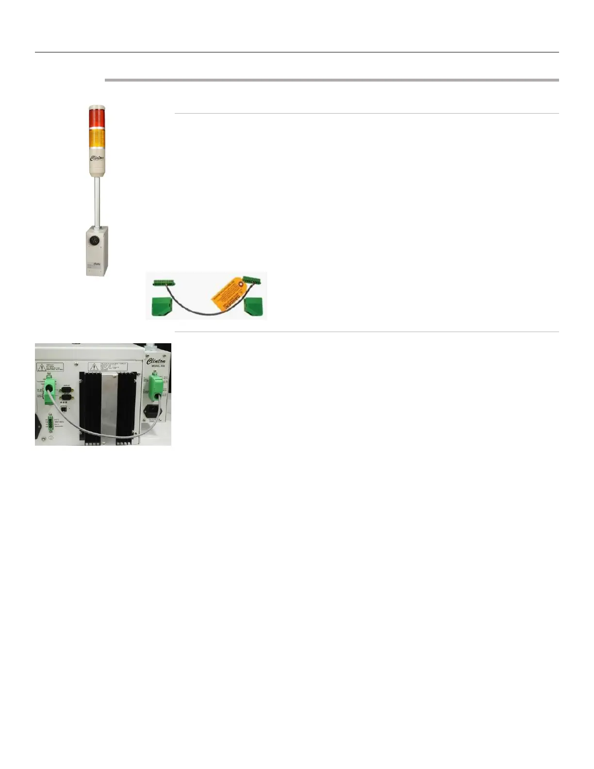
Connecting the X3B (Optional)
Unpacking the X3B
Remove the following items from the carton:
1. X3B Horn/Light Tower with mounting plate. Note: If the X3B was ordered
for the BD-22 electrode, the carton should contain the BD-22 mounting
plate (part #91243).
2. Power Cord (part #03780)
3. A 4 conductor cable, with a 9-pin terminal block connector on one end
and a 10-pin connector on the other. (part #91247)
Connecting the X3B
1. Decide which side of the spark tester you wish to mount the X3B. Note
that you may have to remove the small plate from the X3B chassis and
secure it to the opposite side so that the green X3B terminal block is
accessible from the spark tester back panel. Mount the X3B using the
mounting plate and the (4) bolts that attach the end guard to the spark
tester, as shown in the picture to the left.
2. Make sure the spark tester is off before wiring to the X3B.
3. Locate the 10-pin green terminal block on the back of the X3B and the 9-
pin terminal block on the back of the spark tester. The X3B is supplied
with a 4 conductor cable. The 10-pin connector will plug into the X3B
terminal block and the 9-pin connector will connect to the spark tester
terminal block. Prior to inserting them, pins 1-5 of the 10-pin connector
should be wired to accessory equipment with 22 gauge or larger, stripped
back 1/4” (6mm) and fed into the green terminal block connector at the
proper pin numbers, as described on the following page. Pins 1-3 of the 9-
pin connector should be wired as described on the following page.
4. When wiring the two units, notice that pins 5-8 on the spark tester are
now being used to communicate with the X3B. The functions of pins 5-8
on the spark tester have now been transferred to pins 1-5 on the X3B
terminal block. When the wiring is complete, plug in the power cords to
both X3B and the spark tester.