Model HF-15B High Frequency Spark Tester
HF-15B Instruction Manual – Page 18
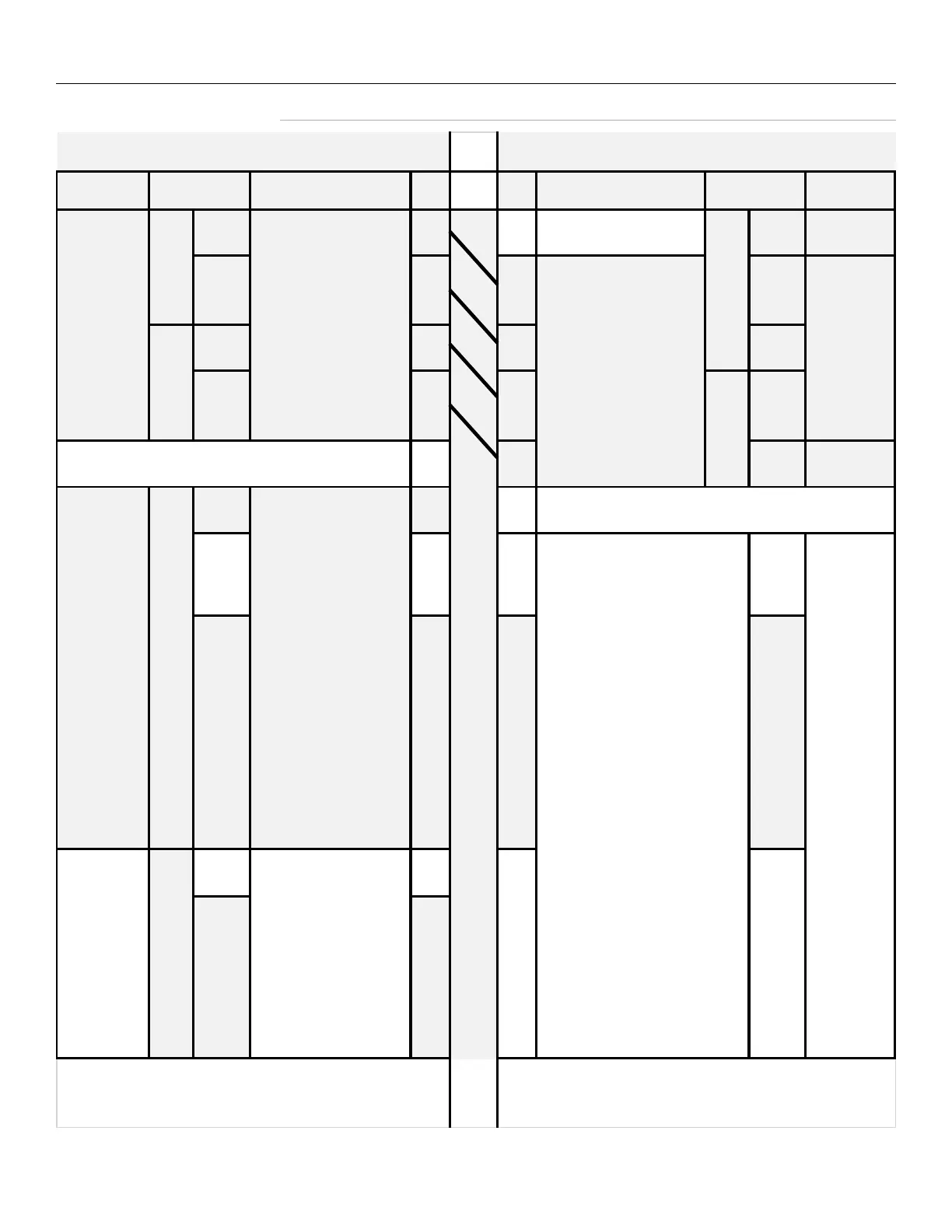
X3B to Spark Tester Connections
Terminal Block
Connections
Terminal Block
Connections
Conductor
COM 10 9 Not Used NC
COM
8 7 NO
6 5 NO
NC 5 4
COM
2
4-Conductor
Cable
Supplied
with X3B (22
gauge or
higher)
To Spark Tester:
Wire pins 10-7 to
spark
tester pins 8-5 on the
spark
tester terminal block
connector
(3) 22 ga.
stranded
conductors
rated 250V,
less than
10 meters
in length,
contained
in a
common
insulating
sheath
Spark Tester Terminal Block Connections
X3B Horn/Light Tower Terminal Block Connections
(3) 22 ga.
stranded
conductors
rated 250V,
less than
10 meters
in length,
contained in
a common
insulating
sheath
To X3A:
Wire pins 8-5 to X3A
pins 10-7 on X3A termi-
nal block connector
4-conductor
cable
supplied
with X3A
(22 gauge or
higher)
**Switches and relays connected to pins 1,2, & 3
should be suitable for 24V low current
applications.
22 ga.
stranded
conductors
rated 250V,
less than
10 meters
in length,
contained in
a common
insulating
sheath
HV ON Indication:
Dry relay contact pins
1&2 will close when
the test voltage
exceeds 500v. For an
indication that HV is
ON in the electrode,
wire a lamp or
auxiliary device* here.
*When connecting auxiliary equipment to dry relay
contacts pins 1, 2, 3, 4, or 5, observe maximum ratings of
120VAC at 2 amps or 240VAC at 1 amp.
External Reset:
To reset the spark tester fault
relay with an external switch,
wire a momentary switch**
between pins 1&3. When
these contacts close, the fault
relay will return to a normal
state. The interval that the
contacts are closed must
exceed 50 ms.
HV Enable:
CAUTION For HV on the
electrode, install a normally
closed switch or relay
contact** between pins 1&2.
This switch or relay should
open automatically when the
wireline stop switch is
activated or be opened
manually by the system
operator when the line stops.
FAILURE TO DO SO COULD
RESULT IN A FIRE HAZARD If
the HV remains ON in the
electrode when your line is
stationary, the wire
insulation in the electrode
will heat and there is a
danger of combustion.
Process Control:
To activate external
lights,alarms or relays*
when a fault occurs, wire
them between dry relay
contact pins 5,4 & 3.
If the Lch function is ON
(set on the front panel),
the dry relay contacts will
remain closed until the
RESET button is pressed or
when pins 1&3 are closed
by remote switch
or relay. If the Lch
function is OFF, the dry
relay contacts will return
to normal state after the
interval known as the
PCd (Process Control
Duration, set on the front
panel) has elapsed.