Model HF-15B High Frequency Spark Tester
HF-15B Instruction Manual – Page 40
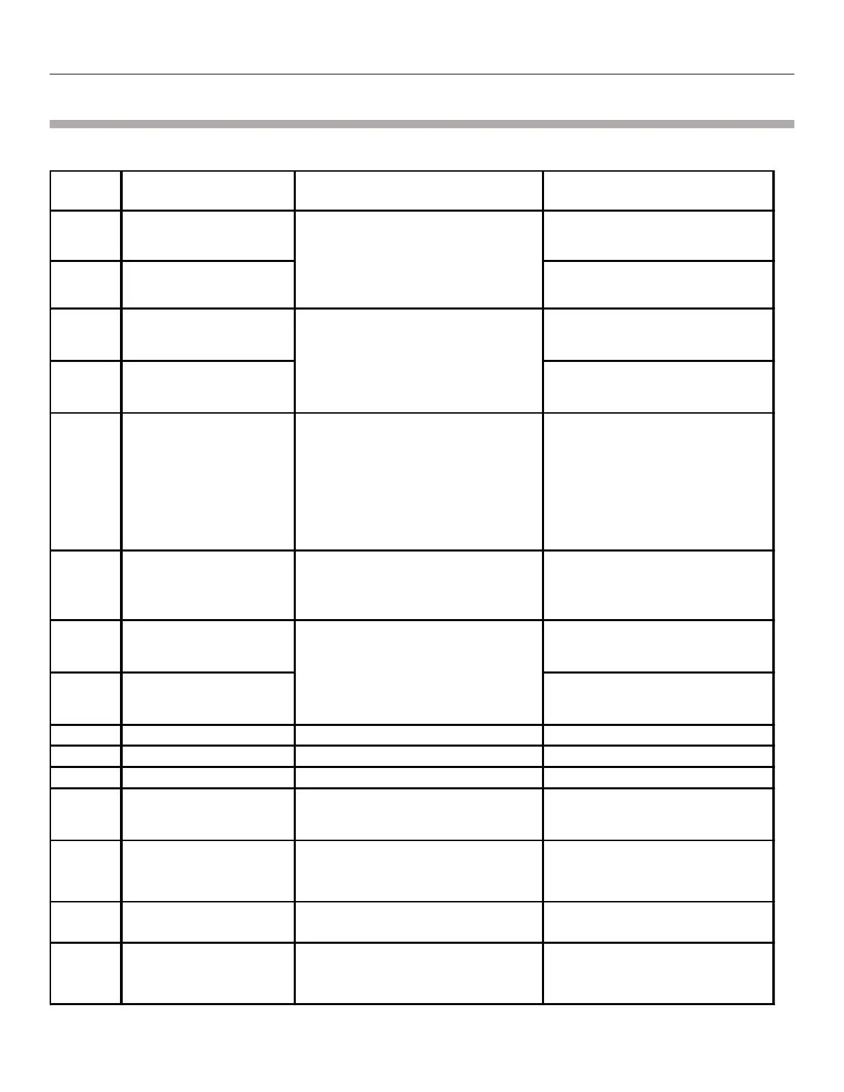
Analog Interface
Analog Interface Pin Functions
Pin
No.
Description Function Notes
Remote Process control
pulse (collector)
Max. Voltage 30V
DC, Max. Current
150mW.
Remote Process control
pulse (emitter)
Max. Voltage 30V
DC, Max. Current
150mW.
Remote Bare Wire
pulse (collector)
Max. Voltage 30V
DC, Max. Current
150mW.
Remote Bare Wire
pulse (emitter)
Max. Voltage 30V
DC, Max. Current
150mW.
When the spark tester is turned ON, a
+12V or a +24V at this pin will change
the voltage setting from LOCAL to
REMOTE. Only then can an analog
voltage control the spark tester voltage
through pin 6. The voltage control on
the front panel of the spark tester will
be disabled.
0-10 input control
voltage
If pin 5 is set to REMOTE, a 0-10V DC
voltage input at this pin changes the
spark tester’s output voltage
proportionally
Remote Fault pulse
(collector)
Max. Voltage 30V
DC, Max. Current
150mW.
Remote Fault pulse
(emitter)
Max. Voltage 30V
DC, Max. Current
150mW.
9 Ground 0- 10v reference ground.
10 Ground
11 Count Reset
12
Count Preset Open
Collector
Current sinking NPN open collector
output.
Max. Voltage 30V
DC, Max. Current
150mW.
This is a +24V DC output which can
be used as a voltage source for the
Opto Isolated outputs.
Chassis ground, cable
shield
This should be used for the cable
shield ground connection
This is a 0-10V DC output
proportional to the spark tester’s
high voltage output.
This output will activate when any fault
type is detected and will remain on for
the Any Fault Alarm Time.
This output will activate when any
bare wire type fault is detected
and will remain on for the Any
Bare Wire Alarm Time.
This output will activate when any
fault type is detected and will
remain on for the Fault Pulse Time.