35
5 - ELECTRICAL CONNECTIONS
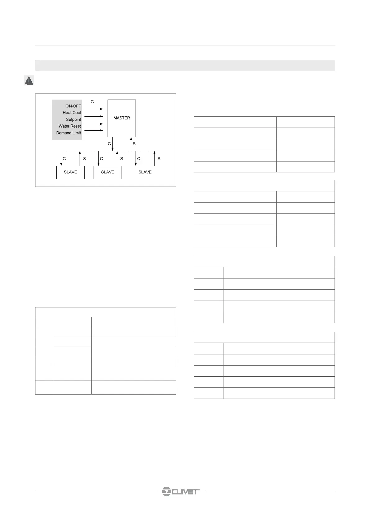
5.29 MASTER SLAVE
1. max : 1 master + 5 slave
2. Perform the electrical connections as indicated in the
diagram
3. OFF unit
4. Set the DIP1 and DIP4 on the master unit, as indicated in
the diagram
5. Set the DIP1 and DIP4 on the slave units, as indicated in
the diagram
6. Switch on the master and slave
7. Set the parameters on the master unit
C controls
S signaling
Unit Total hours
Address1 13536
Address 2 12456
Address 3 14234
Address 4 13765
Unit Total hours
Address 2 12456
Address1 13536
Address 4 13765
Address 3 14234
Unit ranking based on hours of operation
Master unit configuration parameters *
306 NumberMachine N. of units connected in Mininet
308 NumSleep N. of units in standby for rotation
309 ControlAlarm Enables the exclusion of the unit in alarm
310 OffsetMS Offset between the unit SetPoint
313 TimeAlarm Alarm duration before the standby
314 TimerUnitMS Sturt-up delay of 1°capacity step of each
unit in mininet
317 ACSSleepMode Enabling (only) DHW when the unit is in
Sleep
Example:
4 unit
OffsetMS: value of the offset between the setpoint = 1,5 °C
Unit setpoint
Address 2 SetCool = 6,5 °C
Address1 SetCool + Offset = 8,0 °C
Address 4 SetCool + (2xOffset) = 9,5 °C
Address 3 SetCool + (3xOffset) = 11,0 °C
Cool operation
Unit setpoint
Address 2 SetHeat = 45,0 °C
Address1 SetHeat - Offset = 43,5 °C
Address 4 SetHeat - (2xOffset) = 42,0 °C
Address 3 SetHeat - (3xOffset) = 40,5 °C
Heat operation
* Parameters accessible through the installer password 115).
The access by pwd is reserved to qualified personnel;
The parameters changes may cause malfunctions.
The function is not compatible with the boiler option.