31
®
Control
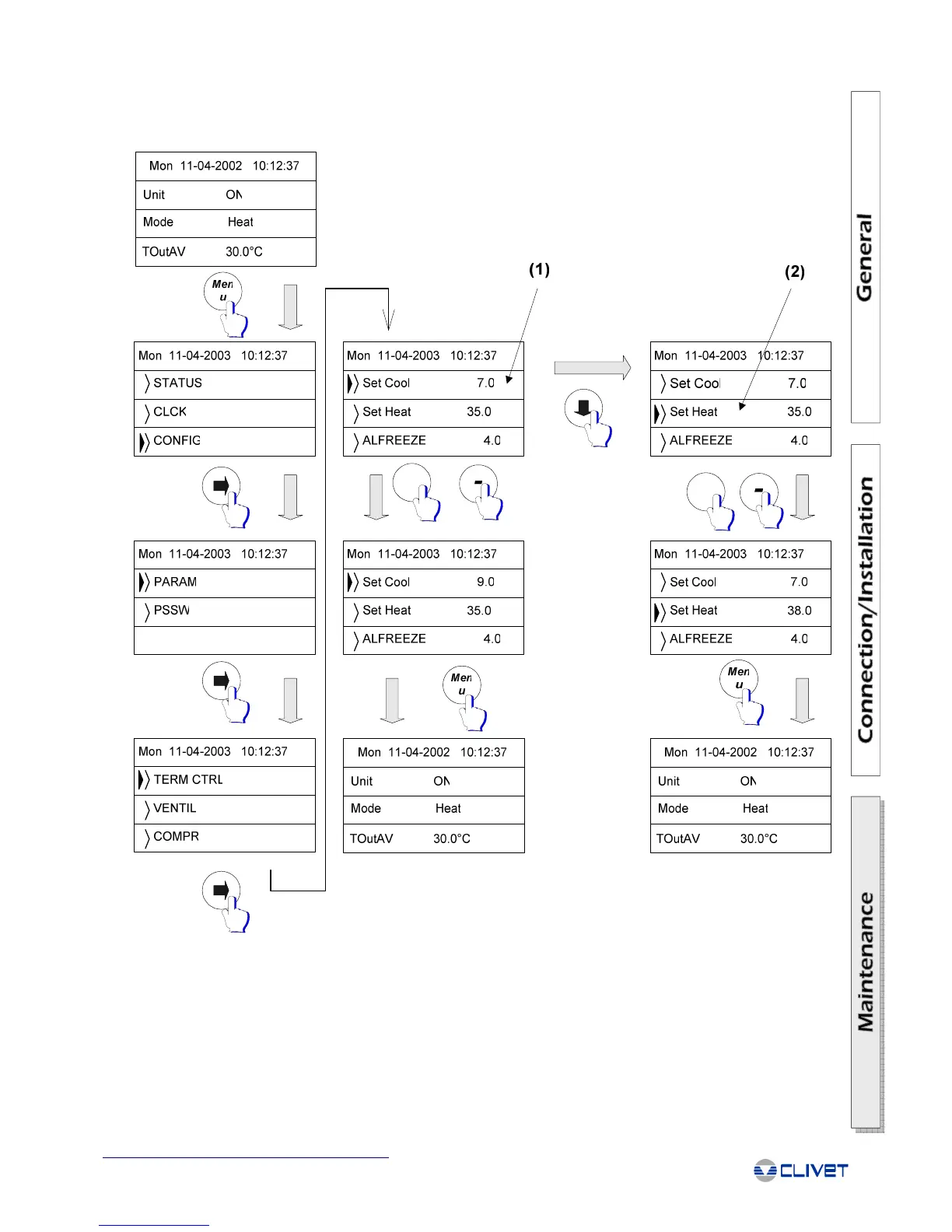
The flow chart shown provides an example of the procedure for accessing the SET POINT parameters. This starts from the main
screen and ends again at the main screen when the procedure is complete. The example assumes that the unit is a heat pump, and
thus describes both the COOLING SET POINT and the HEATING SET POINT.
SETTING THE WORKING SET POINT
SETTING THE ANTIFREEZE SET POINT
The ANTIFREEZE SET POINT parameter is preset by the manufacturer. The antifreeze alarm setting is performed in the same way
as described for setting the working set point, with the exception that the parameter "ALFREEZE" must be set.
1. Cooling set point
2. Heating set point
+
+