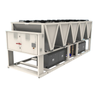
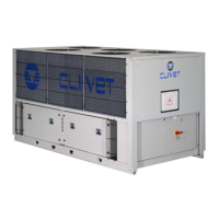
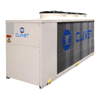
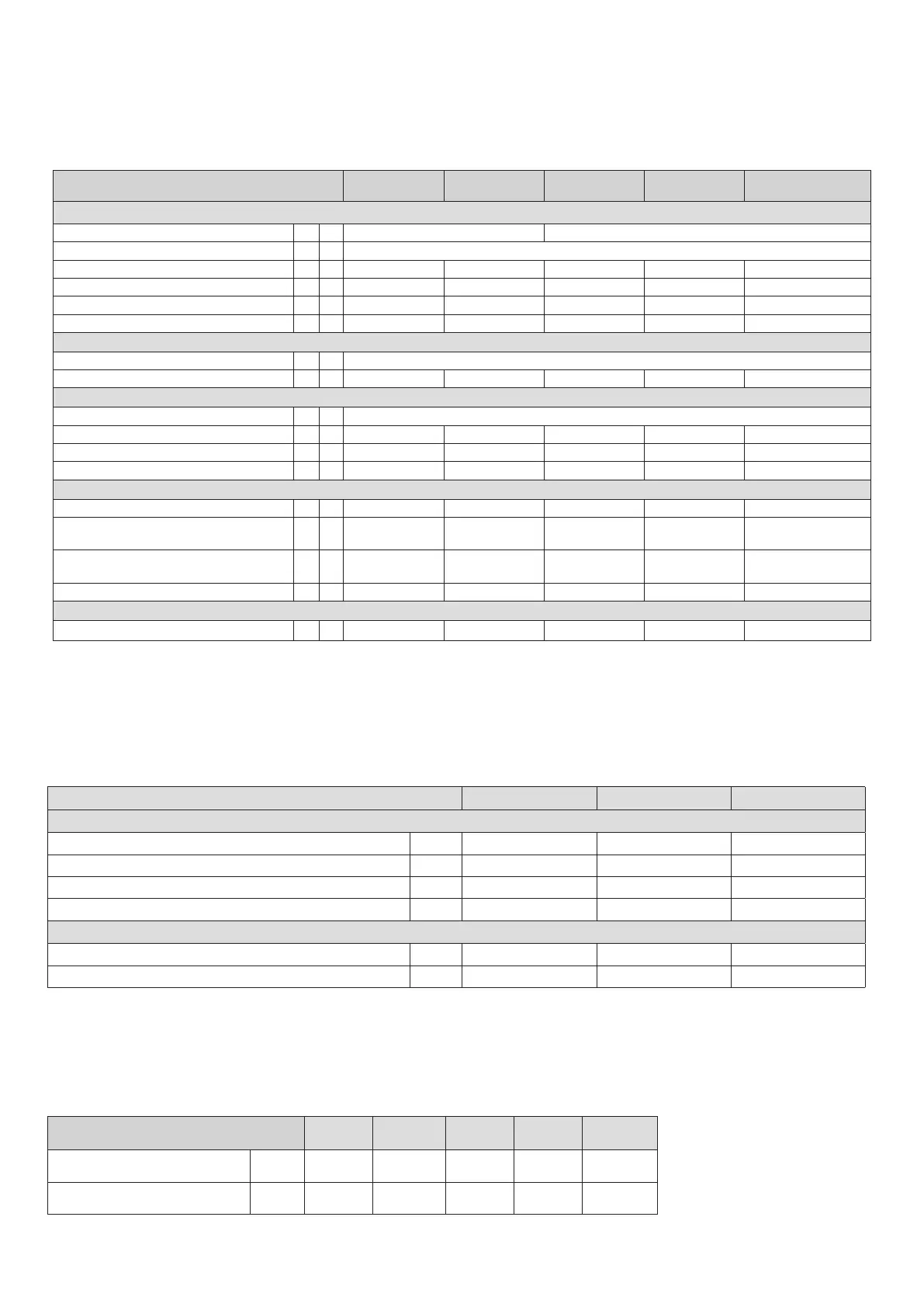
Construction
Size 18.2 20.2 25.2 30.2 35.2
Compressor
Compressor type ROTARY INVERTER SCROLL INVERTER
Refrigerant R32
N° compressor Nr 2 2 2 2 2
Oil charge l 5 5 6 6 6
Refrigerant charge Kg 15,0 15,0 21,0 21,0 21,0
N° circuits Nr 1 1 1 1 1
User side exchanger
Type of internal exchanger 1 BPHE
Water content l 5,7 5,7 7,8 7,8 7,8
External Section Fans
Fans type BRUSHLESS DC MOTOR
N° fans Nr 2 2 3 3 3
Standard air-ow l/s 6889 6889 10333 10333 10333
Installed unit power kW 0,9 0,9 0,9 0,9 0,9
Water circuit
Maximum water side pressure MPa 1 1 1 1 1
Minimum circuit water volume in
heating
2 l 400 400 650 650 650
Minimum circuit water volume in
cooling
3 l 150 150 200 200 200
Total internal water volume l 5,9 5,9 8,0 8,0 8,0
Power supply
Standard power supply 400/3/50+N 400/3/50+N 400/3/50+N 400/3/50+N 400/3/50+N
1. BPHE = plate exchanger
2. Entering/leaving water temperature user side 25/30 °C, external exchanger entering air 2°C (U.R. = 85%) - Minimum water volume that does not consider the
volume of water inside the unit.
3. Entering/leaving water temperature user side 15/10 °C, external exchanger entering air 25°C (U.R. = 85%) - Minimum water volume that does not consider the
volume of water inside the unit.
Overload and control device calibrations
Open Close Value
Refrigerant side
High pressure safety switch kPa 4200 3200 -
Low pressure safety switch kPa 50 130 -
Low pressure safety valve kPa - - 3000
Compressor discharge high temperature safety thermostat °C 115 75 -
Water side
Antifreeze protection °C 4 20 -
High pressure safety valve kPa - - 600*
* The value entered refers to units supplied with a hydronic group installed on board.
Admissible water flow rates
Min. (Qmin) and max. (Qmax) water flow-rates admissibles for the correct unit operation.
Size 18.2 20.2 25.2 30.2 35.2
Minimum ow [l/s] 1,9 1,9 2,9 2,9 2,9
Maximum ow-rate [l/s] 6,4 6,4 6,4 6,4 6,4
General technical data
 Loading...