13
6 – Mounng
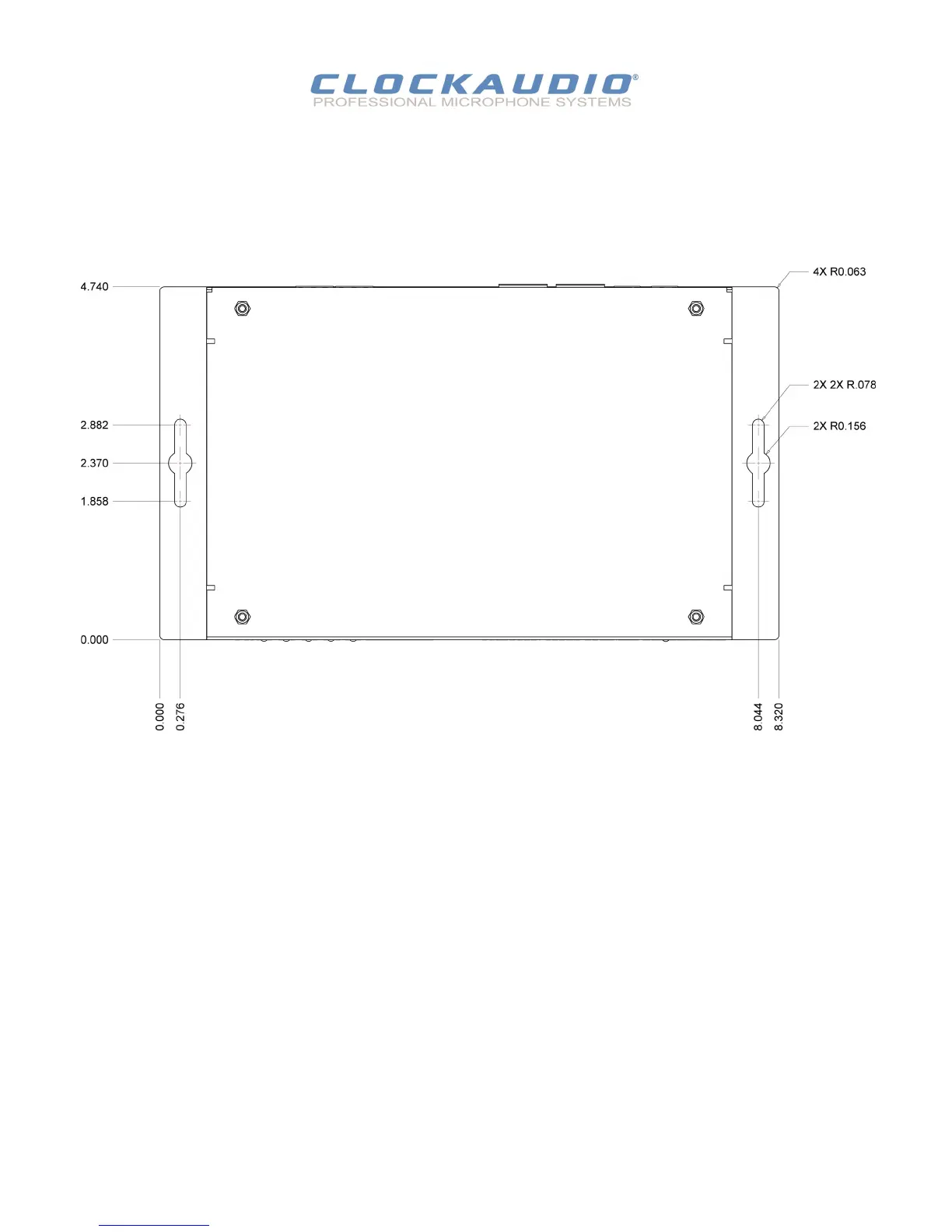
Installaon of the CDT 100 is very straight forward.
It is recommended that the unit be secured to a at surface with a screw through each mounng ange.
Dimensions for mounng are show in the Figure 9 below.
Use a No. 6 screw of a type and size that is applicable to the surface to which the CDT100 will be aached.
All connecons to the CDT 100 should be made before the power is applied.
Aach any audio sources that will be used to the inputs. The inputs are balanced so be sure to check what output type the
source to be connected uses in order to nd how to connect it correctly . (see Hardware Connecons secon).
When powering, using an oponal external supply:
Aach either Dante I/F port to a spare port on the Dante network switch using a CAT 5 cable.
Aach the power supply to the power input jack and then power up the external supply.
If all steps are performed correctly, the power light on the front should be lit. There may also be some acvity on the CDT 100
Dante I/F LED indicators.
With no Dante network, both LEDs will remain o.
If an acve connecon is made, both LEDs will come on and if there is network acvity, the yellow LED will ash.
Figure 9 - Mounng Informaon
CDT100 User Manual
© Clockaudio 2015