14
00001996 (REV AC) 627NH October 2014
POWER SUPPLY AND ELECTRICAL
CONNECTIONS
The hoist should be connected to a branch circuit which
complies with the requirements of the National Electrical
Code and applicable local codes.
It is recommended, especially for a single phase hoist with
a (1) horsepower motor (.75 Kilowatts), that a line with
adequate capacity be run directly from the power supply to
the hoist to prevent problems with low voltage and circuit
overloads.
For grounding of the hoist, the power cord includes a
grounding conductor (green yellow, G-Y). Before connecting
the hoist to the power supply, check that the power to
be used agrees with the position of voltage change plug
on the voltage change board. The nominal hoist voltage
rating corresponding to the voltage range given on hoist
identifi cation plate is:
Single Speed Units Two Speed Units
Range Nominal Range Nominal
110-120 115 -- --
208-240 230 208-240 230
440-480 460 440-480 460
550-575 575 550-575 575
THREE PHASE HOIST
Unless ordered on a special basis, all single speed/dual
voltage (230/460-3-60, 220/380-3-50 and 220/415-3-50)
hoists are factory arranged to operate on 460-3-60 (or
380-3- 50 or 415-3-50). However, a voltage change board
is provided to easily and quickly change from 460 to 230 (or
380 to 220 or 415 to 220) volt operation. The voltage change
board shown in Figure 12 is located in the hoist as shown in
Figure 13.
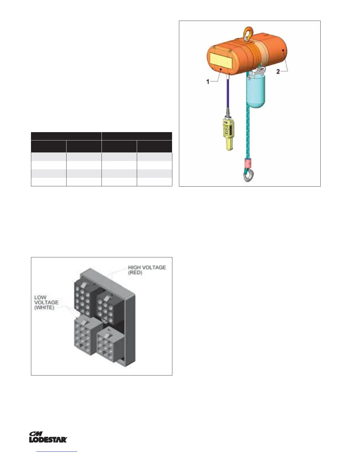
Figure 12. Voltage Change Board
Figure 13. Location of Components
Voltage conversion board is located under back frame
cover (1) for Models A-H and under motor housing cover
(2) for Models J-RRT.
The voltage change board is color coded to indicate high
and low voltage connections. Connecting the 9 and 12 pin
plugs into the “Red” voltage change board receptacles will
connect the hoist for high voltage (380-3-50, 415-3-50 or
460-3-60). To change the hoist voltage to low voltage (208-3-
60, 220-3-50 or 230-3-60) simply remove the 9 and 12 pin
plugs from the “Red” receptacles and insert same into the
“White” receptacles located on the voltage change board. Be
sure to make a notation of the new hoist voltage on the tag
attached to the power cord.
POWER PHASING
Since the motor in a three phase hoist can rotate in either
direction, depending on the manner in which it is connected
to the power supply, the direction of hook movement must
be checked prior to each usage.
NOTE: Serious damage can result if the hook is run to the
upper or lower limit of travel with the hook operating in a
direction opposite to that indicated by the control station.
Therefore, proceed as follows:
1. Make temporary connections at the power supply.
2. Operate (UP) control momentarily. If hook raises,
connections are correct and can be made permanent.
3. If hook lowers, it is necessary to change direction by
inter-changing the Grey lead and the Black lead of hoist
power supply. Under no circumstances should the
internal wiring of the control device or hoist be changed
to reverse hook direction. The wiring is inspected and
tested before leaving the factory.
Do not force the Lodestar Load-limiter to compensate
for improperly adjusted limit switches or reverse voltage
phasing.
 Loading...