MAN. 126 rev.4 Use and maintenance manual S19
16 of 77
2.3.1
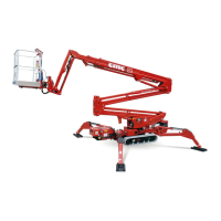
Base chassis frame
1
(
Picture 8
)
High quality steel structure, attached rotating outriggers, hydraulically
driven rubber tracks are adjustable and attached to chassis, designed to
equally distribute the weight of the equipment when booms are in rest
position.
The base chassis frame is equipped with 4 hydraulically operated
outrigger/stabilizers [[2 front stabilizer cylinders2 (Picture 8) and 2 two rear
stabilizer cylinders 3 (Picture 8).
Turret rotation bearing weldment is mounted on the chassis frame 4
(Picture 8), enabling rotation of turret and boom assembly.
2.3.2
Turret
5 (Picture 8)
High quality steel turret is mounted on the rotation bearing. Movement is
accomplished via a heavy duty hydraulic motor (rotation brake is normally
closed), mounted inside the turret. Hydraulic motor and gear box enables
non continuous-rotation of the complete turret approximately 450 degrees.
2.3.3
Pantograph
6 (Picture 8)
The lower boom assembly is designed as a pantograph, composed of two
parallel arms (upper pantograph section 6’
(
Picture 8
)
and lower
pantograph section 6’’
(
Picture 8
)
and pantograph connecting rod 7
(
Picture 8
)
. The booms (rectangular section tubular stages, electrically
welded) and the connecting rod are made of high quality steel. Pantograph
(pantograph lifting and descent) is accomplished via pantograph hydraulic
cylinder 12
(
Picture 8
).
This cylinder is hinged to the turret and the
pantograph upper section. Double acting safety valves are mounted on lift
cylinder.
Pantograph travel is 0° to +65° respective from the horizontal level plane.
2.3.4 Upper telescopic boom
8 (Picture 8)
Upper boom is hinged at the turret 8 (Picture 8) and comprised of three
sections: 1 fixed boom 9 (Picture 8) hinged at the turret and 2 sliding
sections 10 11 (Picture 8).
Sliding telescopic boom sections and or retraction movement of the
telescopic boom is activated by controlling the “hydraulic cylinder inside the
telescopic boom” 13 (Picture 8).
Up and down movement of the telescopic boom is controlled by activating
the “hydraulic cylinder that raises or lowers the telescopic boom.” 14
(Picture 8).
2.3.5
Basket
16 (Picture 8)
Basket is connected to the second sliding telescopic boom through the
horizontally pivoted support 15 (Picture 8), basket base is built of steel,
basket is built with high strength aluminium* tubing. Some baskets are built
with aluminium tubing and covered with fibreglass*; and some baskets are
made completely of fibreglass* construction. Basket is equipped with a
lateral opening for safe operator egress. The lateral opening is self- locking
in order to avoid accidental opening. Basket is equipped with an approved
safety fall arrest belt attachment point, guard-rails are 43” (1,1m) high
safety rails, middle guard-rail and a foot slide protection band along all
the lower sides of the platform. Floor is built with antiskid aluminium plate
including self-draining weep holes in the floor.