MAN.234 Rev.3 ENG - Use and maintenance manual S19HD PRO page
11
of
83
3 Control positions
3.1
Engines ignition station
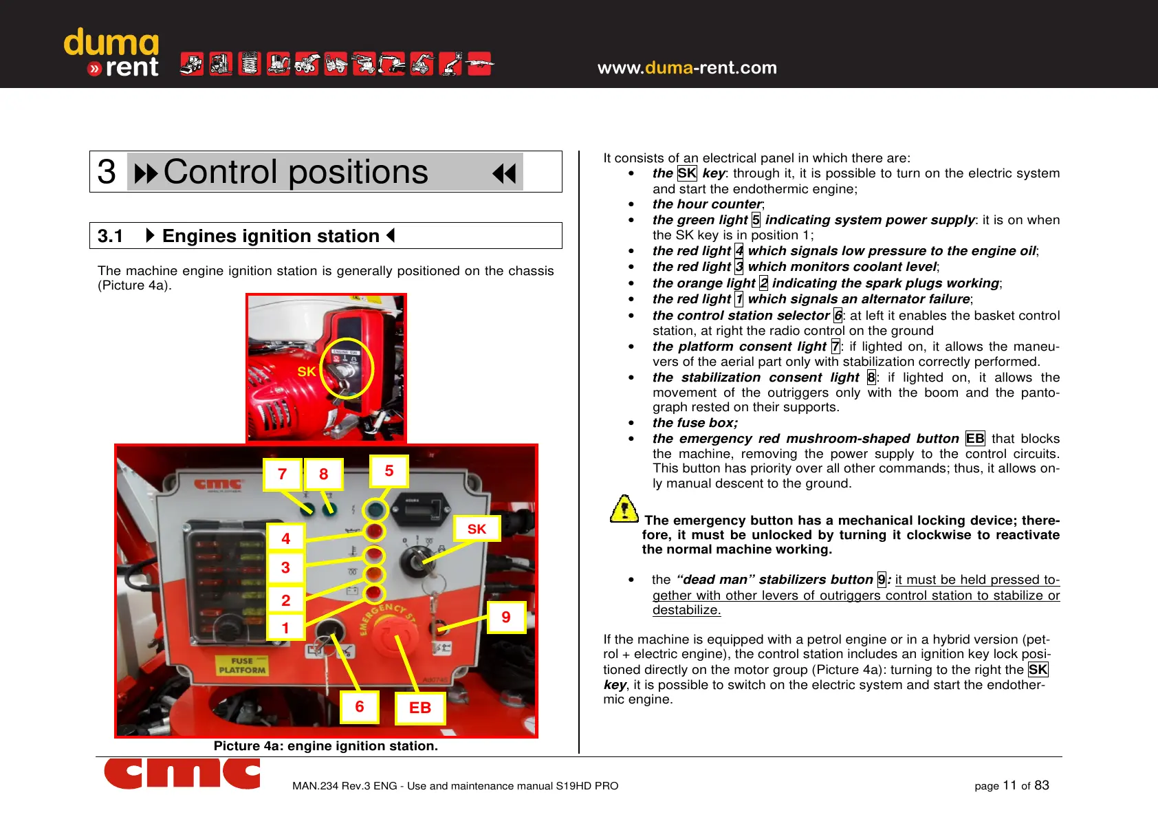
The machine engine ignition station is generally positioned on the chassis
(Picture 4a).
Picture 4a: engine ignition station.
It consists of an electrical panel in which there are:
• the SK key: through it, it is possible to turn on the electric system
and start the endothermic engine;
• the hour counter;
• the green light 5 indicating system power supply: it is on when
the SK key is in position 1;
• the red light 4 which signals low pressure to the engine oil;
• the red light 3 which monitors coolant level;
• the orange light 2 indicating the spark plugs working;
• the red light 1 which signals an alternator failure;
• the control station selector 6: at left it enables the basket control
station, at right the radio control on the ground
• the platform consent light 7: if lighted on, it allows the maneu-
vers of the aerial part only with stabilization correctly performed.
• the stabilization consent light 8: if lighted on, it allows the
movement of the outriggers only with the boom and the panto-
graph rested on their supports.
• the fuse box;
• the emergency red mushroom-shaped button EB that blocks
the machine, removing the power supply to the control circuits.
This button has priority over all other commands; thus, it allows on-
ly manual descent to the ground.
The emergency button has a mechanical locking device; there-
fore, it must be unlocked by turning it clockwise to reactivate
the normal machine working.
• the “dead man” stabilizers button 9: it must be held pressed to-
gether with other levers of outriggers control station to stabilize or
destabilize.
If the machine is equipped with a petrol engine or in a hybrid version (pet-
rol + electric engine), the control station includes an ignition key lock posi-
tioned directly on the motor group (Picture 4a): turning to the right the SK
key, it is possible to switch on the electric system and start the endother-
mic engine.