MAN.234 Rev.3 ENG - Use and maintenance manual S19HD (PRO) page
56
of
83
6 Electrical system
The MEWP is electrically supplied when the key is inserted and rotated in
position 1 (Picture 4).
Periodically check the efficiency of the electrical system: battery, alterna-
tor, regulator alternator charge.
The electrical system is attached to this manual.
Any operation requiring interventions on the components of the ma-
chine, shall carried out by authorized and trained staff.
It is forbidden to replace the components for non-authorized staff.
Many components of the MEWP have been calibrated: a correct
calibration of these parts (which is possible only in C.M.C. or in
authorized Services) is important to assure the safety of the
machine.
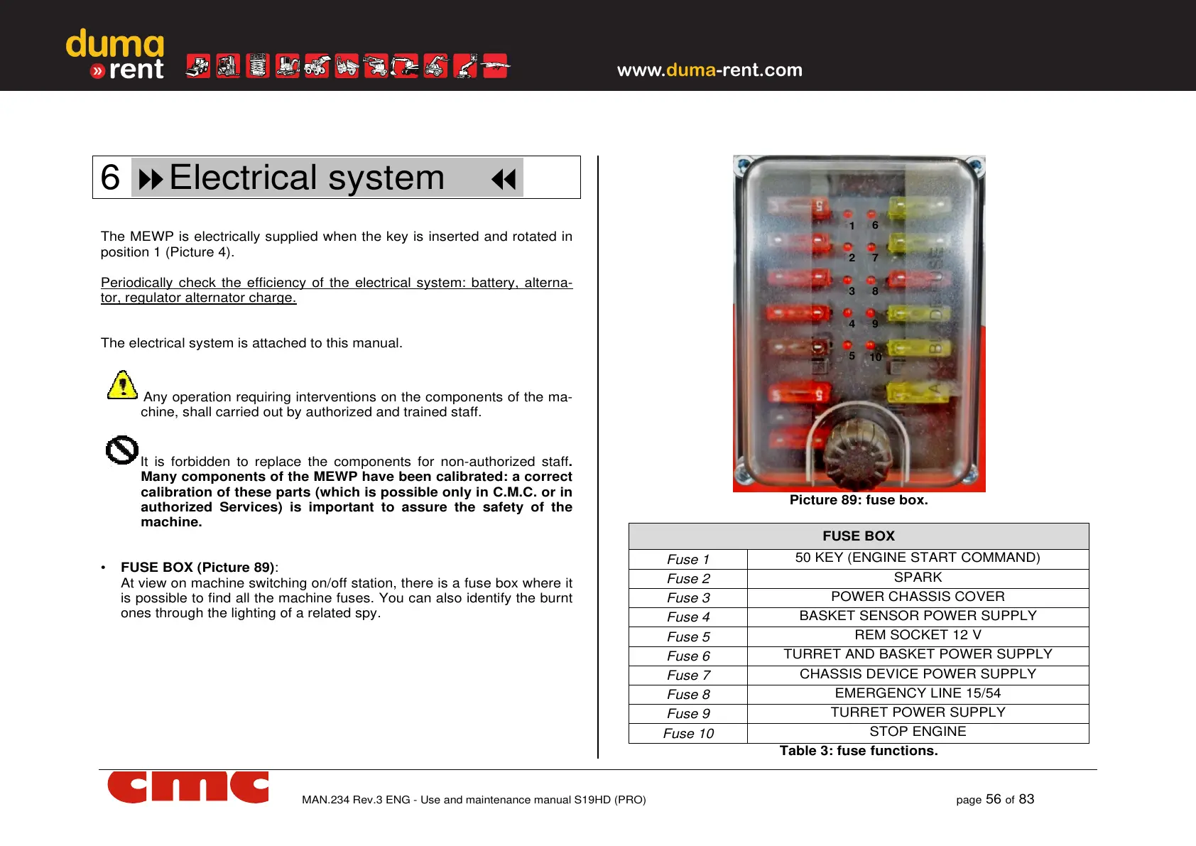
• FUSE BOX (Picture 89):
At view on machine switching on/off station, there is a fuse box where it
is possible to find all the machine fuses. You can also identify the burnt
ones through the lighting of a related spy.
Picture 89: fuse box.
FUSE BOX
Fuse 1
50 KEY (ENGINE START COMMAND)
Fuse 2
SPARK
Fuse 3
POWER CHASSIS COVER
Fuse 4
BASKET SENSOR POWER SUPPLY
Fuse 5
REM SOCKET 12 V
Fuse 6
TURRET AND BASKET POWER SUPPLY
Fuse 7
CHASSIS DEVICE POWER SUPPLY
Fuse 8
EMERGENCY LINE 15/54
Fuse 9
TURRET POWER SUPPLY
Fuse 10
STOP ENGINE
Table 3: fuse functions.
1
2
3
4
5
6
7
8
9
10