AN279
2.4 Description of burning control interface and connection mode
The burning control interface includes two parts: burning and automation control. For manual control burning,
it only needs to connect the chip by pressing the start button. For batch burning, the chip and automaton
control are connected as follows:
1. Burning interface
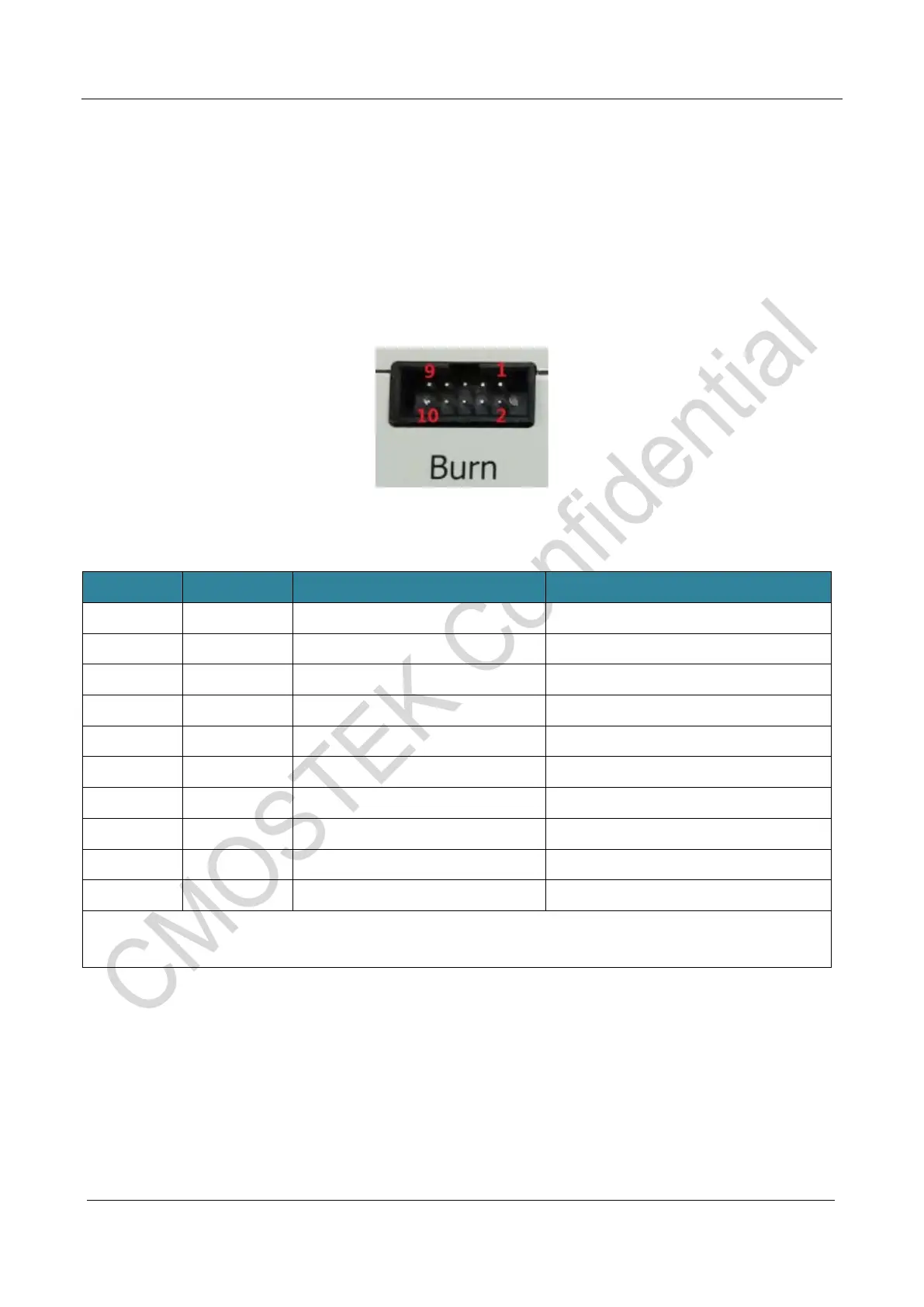
The burning interfaces are shown in the following figure and table:
Figure 6. Burning interface
Table 8. Burning interface description
Pin No. Pin name Description Connect to chip pin
1 CSB Selected signal
2 GND Ground
3 - -
4 VDD Chip power supply
5 CLK RF serial clock signal
6 - -
7 DIO RF serial port data signal
8 - -
9 - -
10 VPP Voltage output regulating
:
Due to the high speed of the burning port signal, connecting line between the recorder and chip needs to
use the same length of flat cable or Dupont line to ensure that the signal timing is correct.
 Loading...