Do you have a question about the COBHAM SAILOR FleetBroadband Series and is the answer not in the manual?
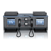
Presents the SAILOR 500 FleetBroadband system, detailing its overview and components.
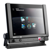
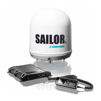
Presents the SAILOR 250 FleetBroadband system, detailing its overview and components.
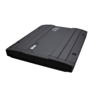
Presents the SAILOR 150 FleetBroadband system, detailing its overview and components.
Provides critical information and warnings before proceeding with the installation.
Explains different types of grounding and their importance for safety and performance.
Explains the meaning of the system's LED indicators for status display.
Details status indicators for the FBB 150 model.
Guides on generating and viewing a diagnostic report for system analysis.
Details how to access and interpret the system's error logs.
Lists various error codes and their meanings for troubleshooting.
Provides a general guide on troubleshooting the FBB system.
Addresses common antenna failure issues and their troubleshooting steps.
Details the removal and replacement procedures for the SAILOR 500 FleetBroadband system components.
Provides steps for uploading software from a computer to the terminal via the web interface.
Explains how to perform a forced software upload using TFTP when web access is unavailable.
Details the procedure for forced software upload using a USB connection.
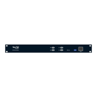
Provides an overview of R&R procedures for the EXPLORER 727 system components.
Provides an overview of R&R procedures for the EXPLORER 325 system components.
| Category | Marine Equipment |
|---|---|
| Type | Satellite Communication Terminal |
| Manufacturer | Cobham SATCOM |
| Frequency Band | L-Band |
| Series | FleetBroadband |
| Antenna Size | Varies depending on the specific model (e.g. SAILOR 150, SAILOR 250, SAILOR 500). Refer to specific model datasheet. |
| Interface | Ethernet, Serial |
| Operating Temperature | -25°C to +55°C |
| Weight | Varies depending on the specific model. Refer to specific model datasheet. |
| Dimensions | Varies depending on the specific model. Refer to specific model datasheet. |