Code Blue
•
259 Hedcor Street
•
Holland, MI 49423 USA
•
800.205.7186
•
www.codeblue.com
GU-157-AApage 22 of 76
CB 1 Series
Administrator Guide
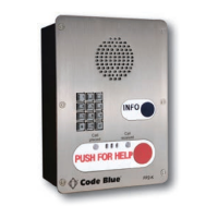
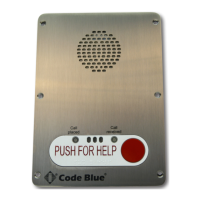
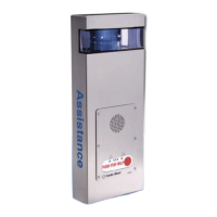
14 CB 1-e and CB 1-s Installation Instructions
1.0 FOUNDATION (see anchor bolt installation instructions)
2.0 SET THE UNIT
2.1 Screw one set of nuts and washers onto the anchor bolts – After the foundation has set,
screw one set of nuts followed by one set of washers onto the anchor bolts. Set the nuts so the
lowest washer is about 2½ inches above the concrete and at an even height. To accomplish
this, use a small level and check from front to back, side to side and diagonally. These nuts
are NOT adjustable after the unit is in place. The bottom edge of the Code Blue unit will be
½-inch above the concrete when installed.
IMPORTANT: The leveling of the bottom nuts is crucial to the leveling of the unit. A small error
in the adjustment of these will be magnied after installation.
IMPORTANT: A ½-inch minimum air gap is required between the foundation and the unit.
Moisture problems may result if this condition is not complied with.
2.2 Set the Code Blue unit on the anchor bolts – Align the phone plate in the desired direction
and lift the Code Blue unit over the anchor bolts. The unit may be lifted using the bracket on
the inside of the unit. Note that the unit weighs approximately 330 pounds. Use appropriate
lifting materials and methods to avoid possible injury and/or damage.
2.3 Secure the Code Blue unit – Access the mounting studs through the door on the side of the
unit. Place the second washer, then nut and tighten the mounting nuts onto the anchor bolts.
This may be more convenient if a long socket, extension and universal joint is used to tighten
the hardware.
3.0 INSTALL THE AREA LIGHT (CB 1-s only)
3.1 Remove packing material – Remove all packing material and ensure that the bulb is tight.
3.2 Install the light xture – Place the xture on the bracket, just below the lens at the top of the
unit.
3.3 Connect the cord – The power cord must be plugged into the plug near the bracket at the
top of the pedestal.
4.0 INSTALL THE DOME TOP ASSEMBLY
4.1 Remove the clear Lexan dome from the black metal casting. The casting complete with strobe
should be brought to the top of the unit (pedestal) where the wiring will be connected (match
black and red wire connectors; match yellow to yellow connectors). After the wiring is complete,
set the white disc on top of the lens located inside the unit (CB 1-s only). Set the casting on
top of the pedestal and fasten the casting to the bollard by reaching through the openings and
tightening the three 10-24 X 1-inch stainless steel thumbscrews against the inner wall. Finally,
reattach the clear Lexan dome to the black metal casting with the security screws provided.
NOTE: Take care not to overdrive the security screws against the Lexan as fracturing may occur.
5.0 WIRING (refer to additional wiring instructions for the CB 1-s)
5.1 Ground – The ground (green) wire should be stripped and fastened to the supplied grounding
lug.
See diagrams next page